Table of Contents
Advertisement
Quick Links
Advertisement
Table of Contents

Related Manuals for Milltronics Mercap MCP01 S series


Summary of Contents for Milltronics Mercap MCP01 S series
- Page 1 MERCAP Instruction Manual June 2001...
- Page 2 Contact SMPI Technical Publications at the following address: Technical Publications Siemens Milltronics Process Instruments Inc. 1954 Technology Drive, P.O. Box 4225 Peterborough, Ontario, Canada, K9J 7B1 Email: techpubs@milltronics.com For the library of SMPI instruction manuals, visit our Web site: www.milltronics.com © Siemens Milltronics Process Instruments Inc. 2001...
-
Page 3: Table Of Contents
Table of Contents Introduction ........ Introduction ................................................3 3 3 3 Introduction Introduction ....................................................Identifications and Abbreviations....................3 Technical Specifications ........ Technical Specifications ......................................5 5 5 5 Technical Specifications Technical Specifications ........ - Page 4 Additional universal command specifications ..............45 Additional common-practice command specifications.............45 Transmitter specific commands....................47 Appendix B: Tables Appendix B: Tables ........ Appendix B: Tables Appendix B: Tables ....................................................................................54 54 54 54 .....
-
Page 5: Introduction
Introduction The Mercap system is a high performance, level measurement instrument consisting of a sophisticated, easy-to-adjust, transmitter (MST9500) combined with measurement electrodes and process seals designed to accommodate numerous configurations. The electrode, comprised of a measurement section and an active shield section, is the primary sensor of the system, and it indicates the electrical capacitance value of the measurement section relative to the environment (tank wall, stilling well, or conductive material). - Page 6 Page 4 MERCAP – INSTRUCTION MANUAL 7ML19981CM01.1...
-
Page 7: Technical Specifications
Technical Specifications Electrodes Process connections Screw mounting: NPT, BSPT, JIS. Flange mounting: ANSI, DIN Process material: C 22.8 N, AISI 316 L, Monel 400, Hastelloy C22 Probe diameter (mm/inch): 9/0.35 (cable), 16/0.63 (rod), or 24/0.95 (rod) Probe length (mm/inch) Rod version: 5500/216 Cable version: 35000/1378... - Page 8 Temperature stability: 0.15 pF (0pF) or <0.25% (typically <0.1%) of actual measurement value, whichever is greater over the full temperature range of the product. Non linearity and < 0.1% full scale and actual measurement respectively reproducibility: Accuracy: <0.1% of actual measurement value •...
-
Page 9: Electrodes And Process Connections
Electrodes and Process Connections This section of the manual is designed to assist in the determination of the best possible probe configuration for your application. Therefore, we discuss the electrodes and process connections before the instrumentation and the operation procedures. When configuring the unit to your application, use the sample configurations below as your criteria. -
Page 10: Characteristics
Characteristics The following characteristics apply to all general connection configurations: • The standard Mercap insulated electrode is designed for use in both conducting and non-conducting liquid applications. • All electrodes consist of an active shield portion and a measurement portion, which combine to form the complete electrode. -
Page 11: Mercap Configurations
Enamel probes are suggested when process temperature exceeds 200 °C, and/or in combination with very high pressure. : : : : Note Consult Milltronics for chemical applications other than water. Process Connection and Seal Configuration of Mercap Process Connection Process Connection... -
Page 12: Examples Of Mercap Level Instruments
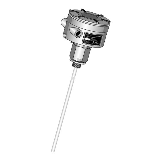
Examples of Mercap Level Instruments The following graphics illustrate the variation in configurations available for the Standard series, Level and Interface series, and Sanitary series Mercap level instrument. Note : All measurements are given in millimeters/inches. Standard Level Version (Mercap MCP01) This is the most common version of Mercap and is available with the following features: •... - Page 13 S-Series Cable Version S-Series Cable Version (with anchor) ∅160 (6.3”) Transmitter Enclosure 120 (4.72") Seal Gland 55 (2.17") Threaded Process Connector Insertion Inactive Length See Order Part +175 (6.9") Instructions Insertion PTFE Insulation Insertion Length Length ∅9 (0.35") 125 (4.9") +/-Varies Tensile Weight Dimension...
- Page 14 MCP01 (Standard) S-Series: Welded and Machined Flanged Versions S-Series Welded Flange S-Series Machined Flange Insertion Length +185 (7.28") TIG Weld Insertion Length +185 (7.28") Active Shield Active Shield Insertion Length Insertion Active Length Length Active Length Inactive Tip Inactive Tip 40 (1.57") 40 (1.57") ∅16 (0.63”)
- Page 15 MCP01 Standard D-Series: Machined Flanged Versions D-Series DD-Series ∅160 (6.3") ∅160 (6.3") Transmitter Transmitter Enclosure Enclosure 120 (4.72") 120 (4.72") Seal Gland Seal Gland 65 (2.56") holes Flange Process Connection 120 (4.72") holes Flange ∅k Process ∅D Active Connection Shield ∅k PTFE Lining Active...
- Page 16 SD-Series Probe/Thermal Isolator ∅160 (6.3") ∅160 (6.3") Transmitter Transmitter Enclosure Enclosure 120 (4.72") 120 (4.72") Seal Thermal Dependent on Gland Isolator extension length Seal 120 (4.72") Gland holes holes Flange Flange 85 (3.35") Process Process Connection Connection ∅k ∅k ∅D ∅D Active Shield Active Shield...
-
Page 17: Interface And Level Version (Mercap Mcp 02)
Interface and Level Version (Mercap MCP 02) This version is designed specifically for interface level where a long distance active shield portion of the electrode is required (up to 35 meters) before the measurement portion of the electrode begins. This type of application is common in large storage tanks for oil where the bottom of the tank invariably has a layer of water below the oil. - Page 18 Sanitary Level Version (Mercap MCP 03) The hygienic design includes threaded and tri-clamp versions for use in the food and pharmaceutical industry. MCP03: Sanitary Versions Sanitary Thread Coupling Sanitary Tri-Clamp ∅160 (6.3") Transmitter Enclosure 118 (4.65") Seal Gland Seal Gland IDF Nut Tri-clamp Connection...
-
Page 19: Flanges
Flanges øL øK (n holes) øD Flange Standards Note • All Sizes: • One (1) inch: ^ 25.4mm • Details: See drawings, technical data, and measuring probe details 7ML19981CM01.1 MERCAP – INSTRUCTION MANUAL Page 17... - Page 20 (725 psi). This curve is typical for water only, for other, more aggressive chemicals the derating curve will be more severe. Reference Product: Water Note : For high temperature and pressure ratings for the Enamel probe, please contact your Siemens Milltronics representative. Page 18 MERCAP – INSTRUCTION MANUAL 7ML19981CM01.1...
-
Page 21: Applications Examples
Applications Examples Generic Application Calculations The capacitance expected in a cylindrical tank with a probe centrally mounted is estimated using the following formula: C=ξ _air 24x0.95 pF = 12.7pF Mercap Log (1/0.016) 0.25m In which C = capacitance value in pF ξ... - Page 22 A similar example in inches yields the following: =ξ _oil-ξ _air 7.32x4.5 = 16.6 pF increase for oil Log (60/0.63) So for this slightly larger tank, the Mercap capacitance ranges from 16.6 pF to 33.2 pF. 6" (0.5ft) So on calibration: 16.6 pF ≅...
-
Page 23: Flow-Through Electrode
Flow-Through Electrode The Mercap flow-through electrodes provide the following multi-functional applications for a liquid pipe system: • quality measurement • interface measurement and detection • product presence detection The measurement occurs without placing an obstacle in the product line and uses capacitance to determine the physical characteristics of the product. -
Page 24: Ftf Series
FTS Specifications Process Connections: Sandwich, acc. ANSI and DIN standards (table p. 23) Fitting length: 55mm (2.1") Material: AISI 316L or carbon steel C 35 Max. Pressure: 50 bar (dependent on pressure rated flanges) Max. Temperature: 200°C (398°F) Lining: PTFE (1mm thick) Transmitter Enclosure Aluminum ø160mm (6.3") Waterproof Classification:... - Page 25 FTF Specifications Process Connections: Flange, acc. ANSI and DIN standards (table p. 23) Fitting length: 100mm (3.9") Material: AISI 316L or carbon steel C 35 Max. Pressure: 50 bar (dependent on pressure rated flanges) Max. Temperature: 200°C (398°F) Lining: PTFE (1mm thick) Transmitter Enclosure: Aluminum ø160mm (6.3") Waterproof Classification:...
-
Page 26: Mst9500 Transmitter
MST9500 Transmitter Operating Principles The instrument's MST9500 transmitter measures the capacitance of a sensor/electrode relative to the reference electrode (often the tank wall) and transforms it to a 4-20 mA signal. Applications include level measurement, level detection, flow measurement, and flow detection. -
Page 27: Installation Installation And Interconnection Installation And Interconnection
Note : Damage or removal of the sticker voids the warranty for the MST9500. In most cases, the transmitter is in a Milltronics-supplied metal housing, providing reliable operation in environments with dust, moisture, and high frequency interference. The electronics operate at temperatures ranging between -40°C to 85°C, which means that protection equipment, such as sun shields, are not normally required. -
Page 28: Interconnection
Incorrect power connection will not damage the MST9500. However, it can lead to a larger current (~40 mA) through the loop, and it will not operate with incorrect polarity. The MST9500 is isolated from the power supply that provides for the opportunity of grounding either line (positive or negative) if requirements for Ex safety are followed and the power supply voltage is less than 33 Vdc. -
Page 29: Connection Diagrams
Connection Diagrams XP∗ (Cenelec) Version Push Button Command Selection Switch Connector Measuring Signal Ground 4-20 mA loop connection 1 = positive wire (+) 2 = negative wire (-) Ground GP* (FM/CSA/Cenelec) Version / IS* (FM/CSA/Cenelec) Version / XP* (FM) Version Push Button Command Selection Switch Connector... - Page 30 The MST9500 is equipped with three terminals, two of which are intended for connecting loop power instrument cables. This connection is protected against incorrect polarity. The third terminal allows the measurement of the current in the instrument cable with any digital current meter instrument, without breaking the loop circuit.
-
Page 31: Factory Settings
AO1(PV) 4-20 mA is 0-100% "customer input data via HART" DESCRIPTOR "customer input data via HART" MESSAGE "Milltronics" DATE "customer input data via HART" SENSOR SERIAL NUMBER "customer input data via HART" FINAL ASSEMBLY NUMBER "customer input data via HART"... -
Page 32: And Grounding
Applications and Grounding Several common applications appear in this section. Common applications are separated into two types: those with System Grounding and those with Safety Grounding. System Grounding (referencing) The correct operation of the measuring system depends on the correct method of grounding. Make sure that there is a reliable connection to the reference electrode (usually a metal tank). - Page 33 Cathodically Ground lug Protected Metal Tanks Cathodically protected metal tanks are never directly grounded. However, the impedance of the supply source is so low that this does not cause any problems. The connection of the MST9500 in such a situation can be realised as shown here.
- Page 34 Safety Grounding The application, in combination with the connected instruments, determines the safety grounding. The MST9500 transmitter does not have any special requirements due to the galvanic separation between the measurement section and the loop section. The characteristics of DCS can vary. Some DCSs measure the current through the loop compared to a common 0 Volt point, others measure in the positive wire or connector.
- Page 35 However, if you do not want a direct grounding of the negative connection, and in the case of Ex applications where the DCS measures in the negative connection, and that wire cannot be grounded, a barrier type as shown in Example 3 is required. Example 3 Stahl barrier: 9002/13-280-110-00 (or equal)
- Page 36 Example 5 Stahl barrier: 9001/01-280-110-10 (or equal) When Ex applications are using an Ex approved supply unit, the barriers are not used and grounding is optional. Page 34 MERCAP – INSTRUCTION MANUAL 7ML19981CM01.1...
-
Page 37: Start-Up
Start-up Capacitive measurement requires adjustment of the instrument based on the application conditions. Two types of adjustment methods are available: • push-button • HART™ Push-Button Adjustment If it is possible to adjust the level of the tank as required to the 0% and 100%, the MST9500 transmitter can be set very easily using the push-button. -
Page 38: Adjustment Using Hart Tm
Adjustment using HART The MST9500 transmitter can be adjusted using HART , with a HART communicator, a laptop running Cornerstone or with the Host system (D.C.S.). The local circumstances determine the manner in which adjustment takes place. If the circumstances allow the product to be brought up to the 0% and 100% point level, adjustment is simple. - Page 39 Example 2 In this situation, the capacitance values are known in advance. Switch on the 275 and establish connection with the MST9500. Select: Online Select: Device set-up Select: Diag service Select: Calibration Select: Enter values Select: PV LRV Enter required capacitance value for 0% of the range Select: PV URV Enter required capacitance value for 100% of the range...
- Page 40 Example 4 This situation involves the re-adjustment of the LRV where the actual value is determined to be 17% and the measurement shows e.g. 14%. Assume that the URV was set to 240 pF. Switch on the 275 and establish connection with the MST9500. Select: Online Select:...
-
Page 41: Maintenance
Maintenance This section discusses the test function and maintenance checks. Test function The MST9500 has a test function, which changes the measuring reference, allowing for the operation of the entire circuitry to be checked from input to output. The essence of the test function is changing the measuring capacitance by a fixed factor;... - Page 42 The possible checks can be subdivided in two main groups: Visual Checks inside enclosure clean and dry enclosure sealing intact and working properly (not hardened) all screw connections are tight ground connections inside intact ground connections outside intact no oxidation on push-button and 15 pole source connector no dirt or deposits on coax connector no cable or wires jammed under cover Functional Checks...
-
Page 43: Appendix A: Hart Tm Documentation
Appendix A: HART Documentation This section provides information on using HART HART info Expanded Device Type Code: Manufacturer Identification Code Manufacturer Device Type Code Expanded Device Type Code 21753 Physical Layer Information Field Device Category Capacitance Number (CN) HART Conformance and Command Class MST9500 transmitter Conformance and Command Class summary. - Page 44 Command Command Description Description Usage Usage Command Command Description Description Usage Usage Number Number Number Number Conformance Class #4 Conformance Class #4 Conformance Class #4 Conformance Class #4 Write Primary Variable Range Values Common Practice Set Primary Variable Upper Range Value Set Primary Variable Lower Range Value Reset Configuration Changed Flag Enter/Exit Fixed Primary Var.
-
Page 45: Mst9500 Dd Menu/Variable Organization
MST9500 DD Menu/Variable Organization Root Menu Device Setup Menu Process Variables Auto Calibration Menu Device setup menu Sensor digital value Process variables Applied rerange PV digital value Input percent range Diagnostics/service Keypad rerange PV upper range A0 analog value Basic setup menu Zero correction value PV maximum recorded... -
Page 46: Hart Tm Response Code Information
HART Response Code information Additional response code information, Second Byte. Bit #7: Field Device Malfunction When the transmitter detects a malfunction, the Analog Output will be set in a fault state. Bit #6: Configuration Changed When any of the settings in EEROM is changed either by a write command or by manual ZERO or SPAN adjust, this bit is set. -
Page 47: Additional Universal Command Specifications
sent to the transmitter will be saved automatically in the non-volatile memory upon receipt of the Write or Set Command. Command #39, EEPROM Control, is not implemented. MultiDrop operation This revision of the MST9500 transmitter supports MultiDrop Operation. Burst mode This revision of the MST9500 transmitter does not support Burst Mode. - Page 48 Command #41 Perform Transmitter Self Test The Self Test for the MST9500 will commence as soon as the response from the transmitter is complete and during this time the Primary Variable Value and thus the Primary Variable Analog Output remains frozen at the level existing at the initiation of the test. The test requires about 10 seconds to complete and tests if the measuring circuit operates as expected.
-
Page 49: Transmitter Specific Commands
Transmitter specific commands Command #128 Set Alarm Select This command specifies the state of the Primary Variable Analog Output in case of device malfunction. The status of this variable is returned in byte #0 with Command #15 Read Primary Variable Output Information. This command accepts only the values 0 or 1 resp. - Page 50 Command #130 Set Upper Sensor Limit This command sets the Upper Sensor Limit value to the actual P.V. value. Request data bytes None Response data bytes None Command #131 Set Lower Sensor Limit This command sets the Lower Sensor Limit value to the actual P.V. value. Request data bytes None Response data bytes...
- Page 51 Response data bytes Data byte Sensor Limits Units Upper Upper Sensor Limit Sensor Limit Lower Lower Sensor Limit Sensor Limit Data byte #0 Sensor Limits Units Code, 8-bit unsigned integer. Data byte #1-#4 Sensor Upper Limit Value, IEE754 Data byte #5-#8 Sensor Lower Limit Value, IEE754 Command #140 Write S.V.
- Page 52 Response data bytes Data byte Range Units Code S.V. Upper Upper Range Range S.V. S.V. Lower Lower Range Range Data byte #0 S.V. Units Code, 8-bit unsigned integer. Data byte #1-#4 S.V. Upper Range Value, IEE754 Data byte #5-#8 S.V. Lower Range Value, IEE754 Command #141 Return S.V.
- Page 53 Command #144 Reset Recorded P.V. Max./Min. Values This command rests the recorded maximum and minimum values for PV back to a start value, in this case, the current PV value. Request data bytes None Return data bytes None Command # 145 Read Recorded P.V. Max./Min. Values This command returns the recorded maximum and minimum values for PV since the last reset command or the last power cycle.
- Page 54 Command #146 Write Ratio Value for Span This command sets the Span correction level. This is an autocal feature. Request data bytes Data byte Span Span Corr. Level Corr. Level Setting Setting Data byte #0-3 Span Corr. Level Setting, IEE754 Return data bytes Data byte Span...
- Page 55 Return data bytes Data byte Zero Zero Corr. Level Corr. Level Setting Setting Data byte #0-3 Zero Corr. Level Setting, IEE754 Command #149 Read Ratio Value for Zero This command returns the Zero correction level. This is an autocal feature. Request data bytes None Return data bytes...
-
Page 56: Appendix B: Tables
Appendix B: Tables Table A Conversion Range 0 - 100 % Range 0 - 100 % Current in mA Current in Range 100 - 0 % Range 100 - 0 % Range 0 - 100 % Range 0 - 100 % Current in Current in Range 100 - 0 %... -
Page 57: Versus Supply Volts
Table B Total Loop Ω versus Supply Volts highest current 22 mA fixed current lowest current 3.6 mA OPERATION AREA supply voltage (Vdc) Table C Voltage Drop Versus mA For Current Transmitter Operation voltage drop over 250 ohm measuring resistance voltage drop over 280 ohm in barrier... -
Page 58: Appendix C: Approvals
Appendix C: Approvals CE Certificate WRITTEN DECLARATION OF CONFORMITY Siemens Milltronics Process Instruments B.V. Nikkelstraat 10 - 4823 AB BREDA - The Netherlands Declare, solely under own responsibility, that the product Declare, solely under own responsibility, that the product Declare, solely under own responsibility, that the product... -
Page 59: Certificates And Approvals
Certificates and Approvals The Intrinsical Safety Specifications of the MST9500 have been defined and approved as follows: Application Application Specifications Specifications Application Application Specifications Specifications current loop insulated from the measuring circuit 3.6-22 mA internal capacitance can be neglected internal inductance 10 µH maximum supply voltage 30 Vdc... -
Page 60: Control Drawing Fm/Csa Approval Mercap
Control Drawing FM/CSA Approval Mercap Page 58 MERCAP – INSTRUCTION MANUAL 7ML19981CM01.1... - Page 61 Index Abbreviations and Identifications Intrinsical ..............4 list................ 3 Introduction ............3 APPLICATIONS Maintenance SAMPLES ............30 information............39 Applications Examples ........19 MCP01 (Standard) S-Series: Threaded Approvals and Certificates Versions ............10 details..............4 MCP01 (Standard) S-Series: Welded and Cable Machined Flanged Versions ....... 12 requirements ..........26 MCP01 Standard D-Series: Machined Flanged CATHODICALLY PROTECTED METAL TANKS...
- Page 62 Total Loop Ω Versus Supply Volts....55 TEST STARTING WITH HART ......39 Transmitter ............. 5 STARTING WITH THE PUSH-BUTTON..39 OVERVIEW ............24 Test Function SPECIFIC COMMANDS ........ 47 information............39 Vessels Filled with Oil ........19 thermopart ............21 Voltage Drop Versus MA........55 Total Loop .............55 Wetted Parts............
- Page 63 *7ML19981CM01*...
Need help?
Do you have a question about the Mercap MCP01 S series and is the answer not in the manual?
Questions and answers