Table of Contents
Advertisement
Quick Links
Advertisement
Table of Contents

Related Manuals for Milltronics IQ Radar 160


Summary of Contents for Milltronics IQ Radar 160
- Page 1 33455500...
-
Page 3: Table Of Contents
TABLE OF CONTENTS GENERAL INFORMATION About This Manual ....................5 About IQ Radar 160....................6 SPECIFICATIONS IQ Radar 160 ......................7 INSTALLATION Location ........................9 Dimensions......................10 Mounting........................11 Flanged ......................11 Extension Requirements................12 Rod Assembly .....................13 Interconnection ....................14 Terminal Block Layout ................14 Wiring......................15 START UP Overview ........................17 Display and Keypad ....................19... - Page 4 PL-550...
-
Page 5: General Information
IQ Radar 160, detailing the interoperation of the salient features. Applications looks at the IQ Radar 160 from a practical point of view, using a typical application example. Parameters lists the parameters available to you, with a description of their function and use. -
Page 6: About Iq Radar 160
ABOUT IQ RADAR 160 The IQ Radar 160 is to be used only in the manner outlined in this manual. IQ Radar 160 is a versatile process material level monitoring instrument. Material level measurement is achieved using advanced pulse radar techniques. The unit consists of an electronic component coupled to the antenna. -
Page 7: Specifications
SPECIFICATIONS IQ RADAR 160 100/115/200/230 ±15% V ac*, 50/60 Hz, 15 VA Power: *factory set – see device nameplate Interface: optically-isolated 0/4-20 mA into 750 Ω max, analog output: 0.02 mA resolution Dolphin/RS-485 link: refer to Dolphin product specification programmer link:... - Page 8 Environmental: location: indoor/outdoor altitude: 2000 m max ambient temperature: -20 to 60° C (-4 to 140° F) relative humidity: suitable for outdoor (Type 6/NEMA 6/IP 67 enclosure) installation category: pollution degree: Process: ε r > 4 material dielectric: temperature: -40 to 200°C (-40 to 392°F) pressure (vessel): -100 kPa to 1000 kPa (-1 to 10 bar or -10 to 150 psi)
-
Page 9: Installation
INSTALLATION LOCATION Installation shall only be performed by qualified personnel and in accordance with local governing regulations. This product is susceptible to electrostatic shock. Follow proper grounding procedures. Do not mount in direct sunlight without the use of a sun shield. PL-550... -
Page 10: Dimensions
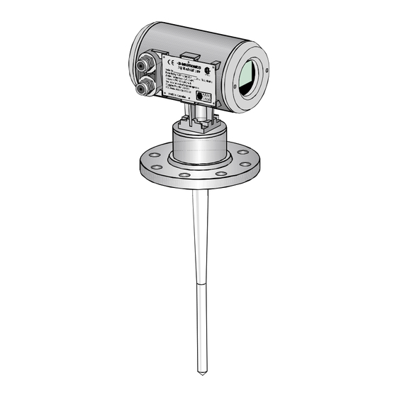
DIMENSIONS 136 mm 211 mm (5.4") (8.3") 75 mm (2.0") (3.0") enclosure/ electronics 41 mm (1.6") antenna 245 mm (resonator) (9.6") 183 mm (7.2") flange or tri-clamp antenna (rod) ◊ 412 mm (16.3") * Flange thickness varies with size and rating. 25mm (1") nominal. Check appropriate standard. -
Page 11: Mounting
MOUNTING FLANGED 1/2" NPT or PG 16 conduit entry wiring access cover supplied ANSI, DIN flange or sanitary tri-clamp customer flanged standpipe to suit tank minimum diameter 2" / DIN 50 standpipe/vessel juncture rod transition For 2" or 3" / DIN 50 or DIN 80, the straight/taper transition of the rod should extend past the standpipe/vessel opening. - Page 12 INSTALLATION...
-
Page 13: Rod Assembly
MOUNTING (continued) ROD ASSEMBLY 50 mm 100 mm extensions standard PL-550... -
Page 14: Interconnection
INTERCONNECTION TERMINAL BLOCK LAYOUT All field wiring must have insulation suitable for at least 250 V. – mA wiring, 14 – 20 AWG, copper wire, shielded – RS-485, 14 – 20 AWG, copper wire, shielded – Line, 12 – 14 AWG, copper wire –... -
Page 15: Wiring
WIRING 4-20 mA, to instrumentation RS-485, to host device V supply, see nameplate Ground shields at one end only. The equipment must be protected by a 15 A fuse or circuit breaker in the building installation. A circuit breaker or switch in the building installation, marked as the disconnect switch, shall be in close proximity to the equipment and within easy reach of the operator. - Page 16 PL-550...
-
Page 17: Start Up
START UP OVERVIEW The IQ Radar 160 has two modes of operation: run and program . When the unit is powered, after installation procedures have been completed, it is programmed to start up in the run mode, to detect the distance from the antenna flange to the target in meters. - Page 18 There are a number of other program parameters that can be changed subsequently or during another programming session. Refer to Parameter Description for a list of the parameters available. When programming has been completed, the IQ Radar 160 can be put into run by pressing or exiting Dolphin.
-
Page 19: Display And Keypad
DISPLAY AND KEYPAD PL-550... -
Page 20: Local Operation
LOCAL OPERATION RUN DISPLAY reading units reading questionable, appears during fail-safe operation auxiliary reading = normal operation = fail-safe operation bar graph representation of material level, 0 to 100% of span PL-550... -
Page 21: Run Keypad
LOCAL OPERATION (continued) RUN KEYPAD In the run mode, the following programmer keys perform the identified functions. Auxiliary Reading Keys Function Keys Auxiliary readings “mA Output Value” “Rate of Change” (in Units/minute) “Fail-safe Time Left” (in percent) “Material Level” X X X “Distance”... -
Page 22: Program Display
LOCAL OPERATION (continued) PROGRAM DISPLAY parameter type (measurement or mA output) parameter value units parameter number PL-550... -
Page 23: Program Keypad
LOCAL OPERATION (continued) PROGRAM KEYPAD Numeric Keys Function Keys values decimal point negative value X X X clear value enter the displayed value parameter scroll-up parameter scroll-down end program session and enable run mode PL-550... -
Page 24: Local Programming
LOCAL OPERATION (continued) Legend Press the associated Programmer Display shown on key on programmer: key: IQ Radar 160: LOCAL PROGRAMMING To Access Program run mode Initial program starts at P000 To Access a Parameter scroll Scroll up or down direct e.g. - Page 25 LOCAL OPERATION (continued) Local Programming (continued) To Change a Parameter Value: Security must be disabled! change Select parameter e.g. P001 = 3 e.g. P001 = 1 clear e.g. field entry = 2 e.g. P001 = 1 PL-550...
- Page 26 LOCAL OPERATION (continued) Local Programming (continued) reset e.g. P001 = 1 Reset to factory value P001 = 3 To Access Run: from program exit and return to run PL-550...
-
Page 27: Operation
OPERATION OVERVIEW IQ Radar 160 is a process material level measuring device using advanced pulse radar technology. The device emits a series of radar pulses and analyses the reflection to calculate the material level. The device consists of an enclosed electronic component, mounted to a flanged antenna component. -
Page 28: Transceiver
TRANSCEIVER The IQ Radar 160 transceiver operates under 1 of 5 sets of preset conditions (P003), summarized as follows: parameter measurement echo filter fail-safe value response verification timer 0.1 m/min slow 1 m/min • 10 m/min • 100 m/min •... -
Page 29: Blanking
BLANKING Near blanking (P800) is used to ignore the zone in front of the antenna where false echoes (e.g. ladder rung) appear as an echo during the receive cycle. This is usually indicated by an incorrect high level reading and can be overcome by increasing the near blanking from its factory set value. -
Page 30: Loss Of Echo
LOSS OF ECHO A loss of echo occurs when the IQ Radar 160 deems that the calculated measurement is unreliable, i.e. the confidence (P805) is less than the threshold (P804). This can be due to such circumstances as high level of electrical noise or poor grounding. -
Page 31: Analog Output
ANALOG OUTPUT The IQ Radar 160 can be programmed to provide an analog output (P200) of 0 to 20 or 4 to 20 mA, and for proportional or inverse span. Programming Upon entering the Program mode, the analog output level holds its prior value. -
Page 32: Fail-Safe
RUN / PROGRAM When the IQ Radar 160 changes from run to program , the transceiver stops operating and the unit no longer responds to the process. The last measurement is stored and the associated reading and mA output are held. -
Page 33: Application Example
5 m from the tank bottom. The empty level is 0 m (bottom) and the full level (span) is 4.5 m from the bottom. The maximum rate of filling or emptying is about 1 m/min. In the event of a loss of echo, the IQ Radar 160 is to go into fail-safe low after 2 minutes. - Page 34 PL-550...
-
Page 35: Parameter Description
PARAMETER DESCRIPTION P000 lock Locks out the ability to change parameter values P001 through P999. The program mode is still active, but restricted to viewing only. The lock is enabled if P000 value is other than 1954. entry: 1954 = unlocked 1954 = locked P001 opera tion... - Page 36 If IQ Radar 160 cannot keep up with the rate of level change, select a faster rate. If the reading bounces around an average value, select a slower rate.
- Page 37 P004 antenna Identifies antenna configuration. entry: 240 = dielectric rod 241 = rod + 50 mm extension 242 = rod + 100 mm extension 243 = rod + 150 mm extension (50 + 100mm) P005 units Determines the units for programming and measurement. entry: 1 = metres 2 = centimetres...
- Page 38 P341 run time View the accumulated number of days the IQ Radar 160 has been operating. P652 offset correction An offset value can be applied to the reading as a correction to the measurement. values: -999 to 9999 P800 near blanking Sets the amount of blanking as measured from the flange face and extending into the measurement range.
- Page 39 Tests the memory. Test is initiated by scrolling to the parameter or repeated by display: PASS = normal FAIL = consult Milltronics P911 mA output value Displays the value from the previous measurement. A test value can be entered and the displayed value is transmitted to the output. Upon returning to the run mode, the parameter assumes the actual mA output level.
- Page 40 P923 distance measurement Displays the reading measurement as though the unit were programmed to read distance (P001 = 3) P999 master reset Resets parameters to their factory setting initiate reset reset complete PL-550...
-
Page 41: Troubleshooting
SYMPTOM CAUSE ACTION display reads level or target is out of check specifications range check parameters application too steamy, re-locate IQ Radar 160 under these conditions range can be adversely increase fail-safe timer, affected. P070 material build-up on clean antenna... - Page 42 P805 liquid surface agitated, material filling decrease measurement response P003 enable filter, echo verification re-locate IQ Radar 160 Reading ‘EEEE’ reading too large re-program ie. empty distance P006 or span P007 Reading response slow P003 setting...
-
Page 43: Maintenance
MAINTENANCE The IQ Radar 160 requires no maintenance or cleaning; however, a program of periodic checks is advised. PL-550... - Page 44 PL-550...
-
Page 45: Appendices
APPENDICES ALPHABETICAL PARAMETER LIST algorithm ....................P820 antenna ....................P004 confidence threshold ................P804 echo confidence ..................P805 echo strength..................P806 empty......................P006 fail-safe material level ................P071 lock ......................P000 long shot number* .................P841 mA output value ..................P911 mA range ....................P200 master reset ....................P999 material ....................P002 measurement response ...............P003 memory ....................P901 near blanking ..................P800 offset correction..................P652... -
Page 46: Programming Chart
PROGRAMMING CHART PARAMETER NAME VALUE P001 Operation P002 Material P003 Measurement Response P004 Antenna P005 Units P006 Empty P007 Span P070 Fail-Safe Timer P071 Fail-Safe Material Level P200 mA Range P652 Offset Correction P800 Near Blanking P801 Range Extension P804 Confidence Threshold P820 Algorithm...
Need help?
Do you have a question about the IQ Radar 160 and is the answer not in the manual?
Questions and answers