
Related Manuals for Milltronics PL-513


Summary of Contents for Milltronics PL-513
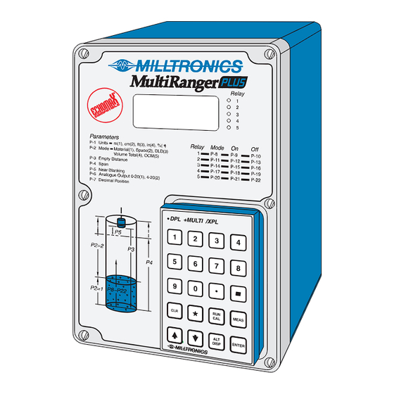
- Page 1 MultiRanger Plus Instruction Manual PL-513 November 1996 33455130 Technology based. Customer driven.
- Page 2 We endeavour to design equipment that is simple to use and reliable in its operation, with the aim of satisfying our customers’ needs. Milltronics has been designing and manufacturing process equipment since 1954. Our fields of expertise include ultrasonic and capacitance level measurement in-line weighing of dry bulk solids and motion sensing.
- Page 3 Multiranger Plus Outline and Mounting Circuit Board Layout Recommendations Interconnection System Diagram Installing the Transducer Selecting Temperature Source Current Output Current Output Isolator Synchronization Power Connections Programmer Start Up General Programmer Keypad Run Mode Program Mode Legend Parameter Entry PL-513...
- Page 4 Pump Miscellaneous Analog Output Applications Simple Level Application Pump Control Applications Pump Run-On Pump Totalizer Application Volume Application Common Tank Shapes Custom Design Tanks Compensation Differential Level Application OCM Applications Single Exponential Palmer-Bowlus H Flumes Other Applications with Standpipes PL-513...
- Page 5 Parameter Description Parameters Troubleshooting General Oscilloscope Troubleshooting Guide Maintenance Maintenance Appendices Sound Velocities Glossary Alphabetical Parameter Listing PL-513...
- Page 6 PL-513...
- Page 7 As well as simple level measurement, the MultiRanger Plus was designed to handle specific applications such as: pumped volume totaling, differential level and open channel flow measurement. PL-513...
- Page 8 PL-513...
- Page 9 Enclosure: » Type 4X / NEMA 4X / IP65 » 160 mm W x 250 mm H x 82 mm D (6.3" W x 9.5"H x 3.2"D) » polycarbonate PL-513 98\06\15...
- Page 10 » max distance to electronics: 365 m (1200 ft) » must be run in grounded metal conduit Temperature Sensor: » Belden 8760, 2 wire shielded » max distance to electronics: 365 m (1200 ft) » can be run with transducer cable PL-513...
- Page 11 (3.2") (5.1") 240 mm (9.5") programmer 228 mm (9") Suitable location for conduit entrances. enclosure Milltronics recommends using a punch for making holes in enclosure. mounting holes customer mounting (accessed under lid screw 4.3 mm (0.17") dia. 4 places Non metallic enclosure does not provide grounding between conduit connections.
- Page 12 IEC 1010-1 Annex H. Relay contact terminals are for use with equipment having no accessible live parts and wiring having insulation suitable for at least 250 V. The maximum allowable working voltage between adjacent relay contacts shall be 250 V. PL-513...
- Page 13 - Trans circuit (ter. 8-9), Coaxial cable RG - 62 A/U - Relays, AC input circuit (ter. 10-28), 12-14 Awg., copper - dc input (ter. 27-28), 14-20 Awg., copper wire, shielded Recommended torque on terminal clamping screws, 5-7 in.lbs (0.56-0.79 Nm). PL-513 98\06\15...
- Page 14 INTERCONNECTION SYSTEM DIAGRAM Milltronics transducer,see MultiRanger Plus Specifications Milltronics TS-3, temperature sensor (optional) mA output customer device relay output customer alarm, pump or control device Maximum system capability. Not all components or their maximum quantity may be required. INSTALLING THE TRANSDUCER...
- Page 15 Note : TB1-2 is internally connected to electrical ground TB1-26. to customer’s equipment maximum loading 350 Ω mA Output - FLOATING (additional to basic wiring) mA output wiring into floating input ONLY. 750 Ω max. Do Not Ground! 06/28/99 PL-513...
- Page 16 Keep wiring as short as possible. Do not route cable along Factory Wired terminal board. optional LIs-1 isolator isolated 4 - 20 mA output wiring into 600 Ω max PL-513...
- Page 17 To synchronize MultiRanger Plus’s and MultiRangers, interconnect the SYNC terminal TB1-4 of the MultiRanger Plus to the SYNC terminal TB1-9 of the MultiRanger. To synchronize more than 8 MultiRangers or MultiRangers with other Milltronics ultrasonic level detection models (e.g. MicroRanger, AirRanger, etc...) consult Milltronics or your distributor.
- Page 18 DC Power 24 V dc Model 12 V dc Model 10 to 15 V dc 18 to 30 V dc Ground MultiRanger Plus (ac Power) via terminal 26 to proper earth / ground. Ground dc model as required. PL-513...
- Page 19 ) must be placed into the front cover recess on the MultiRanger Plus. Be sure to keep it away from objects such as floppy disks that are susceptible to damage from magnetic fields. A programmer need not be ordered with each unit. Check your order if you think that the programmer is missing. PL-513...
- Page 20 PL-513...
- Page 21 Refer to parameters P-76 through P-78. When programming has been completed, the MultiRanger Plus can be put into normal operation by pressing the Run/Cal key. PL-513...
- Page 22 2 service hours (P-25) HRS 3 pump 3 service hours (P-26) HRS 4 pump 4 service hours (P-27) HRS 5 pump 5 service hours (P-28) READ reading (P-76) initiates access into program mode DIST press to view distance (P-78) PL-513...
- Page 23 MEAS a measurement increments display to show the next parameter decrements display to show the preceeding parameter alternates display to show either the parameter number or DISP parameter value enters display as contents of ENTER selected parameter PL-513...
- Page 24 The user may now program the MultiRanger Plus starting at parameter P-1. To direct access a parameter: The display should have a ‘ P- ’ and the number of the currently selected parameter. Current parameter selection e.g. select Select desired parameter. parameter P-20 PL-513...
- Page 25 To access the next parameter: parameter number parameter content displayed displayed e.g. value of P-20 scroll ahead to P-21 value of P-21 To access the previous parameter: e.g. value of P-21 scroll back to P-20 value of P-20 PL-513...
- Page 26 » indicates which parameter is being displayed have entered » appears after pressing run mode "RUN/CAL" key no value » contents of parameter empty or no reading display invalid request » application does not yield requested reading option or spare parameter PL-513...
- Page 27 Upon a loss of echo condition and after the fail-safe timer (P-75) expires, the display will go to fail-safe high at the fill damping rate if P-74 = 1 or to fail-safe low at the empty damping rate if P-74 = 2. PL-513...
- Page 28 The basis is to physically measure the level (measuring tape or sight glass) and enter this value via P-61. The MultiRanger Plus then calculates the sound velocity by comparing the entered physical measurement to its own ultrasonic measurement (empty calibration, P-61) PL-513...
- Page 29 Range extension is entered as a percent of P-3. As range extension reduces the protection afforded by the far end blanking, it should be used judiciously. Avoid excessive range extension as this may reduce the PL-513...
- Page 30 Complete programming of each relay requires two steps. Refer to the Relay Programming Chart Relays. 1 - select a relay function 2 - enter relay ON/OFF setpoints for function options 1-6 and 8-10. - set control parameters for function options 7,11,12,13 and 14. PL-513...
- Page 31 ON setpoint and goes off when the temperature rises to the OFF setpoint. loss of echo : - the function goes on when the fail-safe timer expires. The function goes OFF when a valid echo is received (fail-safe timer is reset). PL-513...
- Page 32 9 blank = cumulative ’ = duty/back-up A = ratio function 8 = level, fixed roster 9 = level, sequential 10 = differential e.g. dE : ’9 = duty/back up sequential pumping de-energize under loss of echo PL-513...
- Page 33 Upon entering the program mode, all pump control relays will be turned OFF. Alarm relays will hold their prior status, but will respond to measurements take when "MEAS" is pressed. PL-513...
- Page 34 L.O.E. L.O.E. L.O.E. L.O.E. L.O.E. pump pump pump pump pump sequential sequential sequential sequential pump on differential totalizer totalizer flow flow sampler sampler time time time time time sampler sampler sampler sampler sampler scanner PL-513...
- Page 35 RELAY PROGRAM CHART Relay 1 Relay 2 Relay 3 Relay 4 Relay 5 Fctn Setpoints Fctn Setpoints Fctn Setpoints Fctn Setpoints Fctn Setpoints Units Relay Function P-11 P-14 P-17 P-20 Alarm : Level P-10 P-12 P-13 P-15 P-16 P-18 P-19 P-20 P-21 In bounds...
- Page 36 2, reads differential head 20 mA or level or flow when if P-6 = 3 empty full empty empty at 0 or 4, reads differential head 20 mA or level or flow when PL-513...
-
Page 37: Security
P-79 to P-88 echo processing and analysis P-89 to P-98 testing P-99 master reset The minimum distance from the transducer face to the target is limited by the minimum near blanking value, P-5, of 30 cm ( 1 ft ). PL-513... - Page 38 SIMPLE LEVEL APPLICATION PARAMETERS General Relays Pump Control Vol. & Disp. Totalizer Custom Filter Conversion units 1 function P-23 submers. P-34 tank P-40 primary P-51 OCM sim. P-60 full P-68 fill damp mode 1 on P-24 1 hrs. P-35 dim. A P-41 time P-52...
- Page 39 SIMPLE LEVEL APPLICATION The most common application of a Milltronics ultrasonic level measuring system is for simple level monitoring, whereby the material level or space measurement is displayed. This may or may not include alarms and mA output. When in the program mode, alarm relays hold their contact state. However, they will respond to measurements taken when "MEAS"...
- Page 40 PUMP CONTROL APPLICATION PARAMETERS General Relays Pump Control Vol. & Disp. Totalizer Custom Filter Conversion units 1 function P-23 submers. P-34 tank P-40 primary P-51 OCM sim. P-60 full P-68 fill damp mode 1 on P-24 1 hrs. P-35 dim. A P-41 time P-52...
- Page 41 ( P\C-24 to 28 ) with respect to the set ratio ( P\A - 24 to 28 )is started. When a pump is to be taken out of service, the pump with the least amount of service hours is stopped. PL-513...
- Page 42 The preset value is immediately stored in memory, however subsequent values are only stored every 4 hours. Thus, after a power failure, the registers will display the last value stored. The registers will automatically reset to 0.000 after reaching a value of 9,999. PL-513...
- Page 43 "1", relay 1 - pump ON P-10 enter " 5", relay 1 - pump OFF P-11 enter option "dE 9" relay 2 - pump function (press "9" and then " " until "dE 9" is displayed) PL-513...
- Page 44 P-30. Only one run-on duration is allowed per interval. The interval is the time period set by P-29 which begins upon return to the run mode or resumption of power. No run-on is allowed during the first interval. Caution: extended pump run-on can lead to cavitation, causing air lock or pump damage PL-513...
- Page 45 24 hour interval, no run-on will occur. After the 24 hour interval has elapsed, whether a pump run-on has occurred or not, the next run-on interval will begin, allowing one run-on cycle. PL-513...
- Page 46 PUMP TOTALIZER APPLICATION PARAMETERS General Relays Pump Control Vol. & Disp. Totalizer Custom Filter Conversion units 1 function P-23 submers. P-34 tank P-40 primary P-51 OCM sim. P-60 full P-68 fill damp mode 1 on P-24 1 hrs. P-35 dim. A P-41 time P-52...
- Page 47 » enter option "1", high total: 4 highest digits of the 8 digit totalizer » enter option "2", low total: 4 lowest digits of the 8 digit totalizer » enter option "5", level It must be noted that only half of the totalizer digits can be accessed or viewed at one time. PL-513...
- Page 48 The mA output responds to the liquid reading only ( level, if P-34 = 0 or volume if P-34 ≠ 0 ). In the event of fail-safe due to loss of echo, the mA output will respond as programmed by P-6 and P-74, but the totalized volume will hold its last reading. PL-513...
- Page 49 100% of a count P-54 press "CLR" enter "0", totalizer preset value, arbitrarily chosen P-55 press "CLR" enter "0", totalizer preset value, arbitrarily chosen P-56 enter "1", totalizer contact control-closure every 10 cu. m to re-enter run mode. CA L PL-513...
- Page 50 VOLUME APPLICATION PARAMETERS General Relays Pump Control Vol. & Disp. Totalizer Custom Filter Conversion units 1 function P-23 submers. P-34 tank P-40 primary P-51 OCM sim. P-60 full P-68 fill damp mode 1 on P-24 1 hrs. P-35 dim. A P-41 time P-52...
- Page 51 "3", span ( inside diameter of tank ) enter ".300", near blanking distance, ( use factory setting ) enter "1", display maximum 1 digit after decimal P-34 enter option "7", tank shape for volumetric conversion PL-513...
- Page 52 A maximum of eleven breakpoints can be defined. Level data is entered in the linear units selected ( P-1 ) and volume data is entered in the tank desired volumetric units. Both of these are referenced to the bottom of the tank. PL-513...
- Page 53 P-34 enter option "9" universal level vs volume press display will show H - 1 - - - - DISP 0.0 0 0 ENTER H - 2 - - - - (then) 1.0 0 0 ENTER PL-513...
- Page 54 ENTER F - 4 - - - - (then) 5 8.4 2 ENTER F - 5 - - - - (then) 1 5 8.9 ENTER F - 5 DISP P - 3 4 to re-enter run mode CA L PL-513...
- Page 55 Enter the "physical measurement". The MultiRanger Plus will now calculate the measurement offset to be used in future level measurements. The offset reading will be automatically entered into P-62 and can now be viewed. P-63 record present sound velocity for reference PL-513...
- Page 56 Enter the "physical measurement". The MultiRanger Plus will now calculate the correct sound velocity to be used in future level measurements.The new sound velocity will automatically be entered into P-63 and P-64, and can now be viewed. to re-enter run mode. CA L PL-513...
- Page 57 PL-513...
- Page 58 DIFFERENTIAL LEVEL APPLICATION PARAMETERS General Relays Pump Control Vol. & Disp. Totalizer Custom Filter Conversion units 1 function P-23 submers. P-34 tank P-40 primary P-51 OCM sim. P-60 full P-68 fill damp mode 1 on P-24 1 hrs. P-35 dim. A P-41 time P-52...
- Page 59 » If set for fail-safe high: the differential reading will display the maximum differential level(P- 4) » if set for fail-safe low: the differential reading will display zero » If set for fail-safe hold: the display will hold its present reading after the fail-safe timer has expired PL-513...
- Page 60 4 - 20 mA output enter "1", display max 1 digit after decimal enter option "4", relay 1 - differential alarm enter "12", relay 1 - rake on This would be used only to initiate the rake control circuitry. PL-513...
- Page 61 Typically, the factory set damping of 32.81 can be used. P-69 enter "393.7", empty damping - same as fill damping P-74 enter option "1, fail-safe high P-75 enter "5", fail-safe timer to re-enter run mode CA L PL-513...
- Page 62 OPEN CHANNEL MEASUREMENT APPLICATION PARAMETERS General Relays Pump Control Vol. & Disp. Totalizer Custom Filter Conversion units 1 function P-23 submers. P-34 tank P-40 primary P-51 OCM sim. P-60 full P-68 fill damp mode 1 on P-24 1 hrs. P-35 dim.
- Page 63 ( P-40 = 4 ) As most OCM applications are outdoors, the use of a temperature sensor is strongly recommended for optimum accuracy. Refer to Functional \ Temperature. PL-513...
- Page 64 If P-39 = 0, alternate readings cannot be momentarily displayed. Pressing the desired key will change the display and hold it there until the next alternate reading is selected. PL-513...
- Page 65 It should also be noted that when operating in the OCM function: percent display, volume conversion ( P-34 ) and convert display ( P-37 ) are inoperative. Empty calibration ( P-61 ) must be clear, i.e. 4 hyphens in the display. PL-513...
- Page 66 » max flow rate - Q max = 4.112 MGD = 4,112,000 gal. / day » max head - H max = 1.61 » transducer is mounted 3 ft above the zero flow level » max flow rate display = 4,112 i.e. one count = 1000 gal. PL-513...
- Page 67 45 sec. » head to read to 1 decimal place » sampler contact every day » head under "1" ( 40 thousand gal / day ) not be totalized » 4 - 20 mA output to respond to flow PL-513...
- Page 68 P-50 enter option "2", mA output responds to flow P-59 enter "1", time sampler control closure once every hour P-74 enter option "2", fail-safe low P-75 enter option ".75", fail-safe timer, 45 sec. to re-enter run mode CA L PL-513...
- Page 69 V - notch or sutro or cipolleti or suppressed triangular proportional trapezoidal rectangular Non-Applicable Weir Profiles Poebing compound approximate contracted exponential rectangular Flows through these weirs may be measured using the universal head vs flow characterization, P-40 = 4. PL-513...
- Page 70 » for rated flows under free flow conditions, the head is measured 15 cm ( 6" ) upstream from the beginning of the converging section. » position the transducer such that it is centered over the flow at a minimum height of 30 cm ( 12" ) above the maximum head. PL-513...
- Page 71 , where: Q = flow rate K = constant H = head x = exponent » position the transducer such that it is centered over the flow at a minimum height of 30 cm ( 12" ) above the maximum head. PL-513...
- Page 72 Dual Range ( nested ) Parshall Flume » two flumes, a larger on top of the smaller, in order to handle a larger range of flows. plan front PL-513...
- Page 73 » for rated flows under free flow conditions, the head is measured at a distance of D / 2 upstream from the beginning of the converging section » position the transducer such that it is centered over the flow at a minimum height 30 cm ( 12" ) above the maximum head PL-513...
-
Page 74: Inches
The same flow table can be used as error is less than 1%. » position the transducer such that it is centered over the flow at a minimum height of 30 cm ( 12" ) above the maximum head. PL-513... - Page 75 The application is to measure the flow across a 4 ft rectangular weir with end contractions. The flow is characterized by the following formula: cfs = 3.33 ( L-0.2H ) H where: cfs = flow in cu ft / sec = length of crest = head PL-513...
- Page 76 - - - - (then) 2.7 0 0 ENTER H - 11 - - - - (then) 3.0 0 0 ENTER F - 11 - - - - (then) F - 11 DISP F - 1 DISP - - - - PL-513...
- Page 77 1 before being displayed or 1 count per thousand cu ft P-53 enter option "2", totalizer decimal point display 2 digits after decimal or resolution equals 1/100th of a count to re-enter run mode CA L PL-513...
- Page 78 APPLICATIONS WITH STANDPIPES In many solids and liquid applications, access to the vessel must be made via a standpipe. In such cases, Milltronics can provide flange mounted transducers that will readily mate to the standpipe. The maximum standpipe length that can be used without additional near blanking ( P-5 not greater than 0.3 m ) is 200 mm ( 8"...
-
Page 79: Table Of Contents
2 = space ( F ) 3 = differential level 4 = volume totalizer ( pump totalizer ) 5 = OCM ( open channel measurement ) empty distance to transducer enter desired amount ( F = 10.00 m ) PL-513... - Page 80 Refer to Functional \ Relays. enter desired option ( F = 0 ) P-9 / 10 relay 1- ON / OFF setpoints enter level in units as selected in P-1 or °C ( F = - - - - ) PL-513...
- Page 81 Refer to Functional \ Relays. enter desired option ( F = 0 ) P-21 / 22 relay 5 - ON / OFF setpoints enter level in units as selected in P-1 or °C ( F = - - - - ) PL-513...
- Page 82 » " pump starts " log » " ratio " setpoint Access is made by scrolling through the levels. press display will show initial access ( service hours ) " pump starts " " ratio " setpoints " service hours " PL-513...
- Page 83 1,234 hours DISP e.g. reset to zero e.g. 0 " service hours " ENTER To set the service " ratio " " ratio " setpoint e.g. 20 DISP e.g. 15 ENTER " ratio " setpoint is now 15 PL-513...
- Page 84 Applications \ Pump Totalizer Application enter: 1 = estimated inflow or discharge volume as added to the pumped volume total ( F ) 2 = estimated inflow or discharge volume is omitted from the pumped volume total. PL-513 07/22/1999...
- Page 85 = non volume - linear level measurement ( F ) = flat bottom = conic or pyramidic bottom = parabolic bottom = half sphere bottom = flat slope bottom = horizontal cylinder, flat ends = horizontal cylinder, parabolic ends = sphere ( cont’d ) PL-513...
- Page 86 2, 3, 4, 5 or the length of one end section in tank shape 7. ( not required for other tank shapes ) enter " dimension A ", in units selected per P-1 ( F = 0000 ) PL-513...
- Page 87 5 = reading level, space, differential, volume or ullage In the run mode, the programmer keys illustrated can be pressed to view alternate readings. The display will return to the reading option selected ( except option 0 ) after momentarily displaying alternate reading. PL-513...
- Page 88 Setting of the subparameters is done in the same way as with the ‘ P ’ parameters. To exit the ‘ H ’ and ‘ F ’ subparameters select any ‘ H ’ or ‘ F ’ parameter return to ‘ P ’ parameters PL-513...
- Page 89 ( refer to Functions \ Analog Output ). Obtain from manufacturer’s specifications. enter " maximum flow rate ", volume units are arbitrary ( F = 1000 ) PL-513...
- Page 90 2 = two digits after decimal ( F ) 3 = three digits after decimal P-50 OCM mA output refer to Functional \ Analog Output enter: 1 = mA responds to head ( F ) 2 = mA responds to flow PL-513 94/09/20...
- Page 91 4 lowest digits of the 8 digit totalizer used in pump totalizer or OCM application. The parameter will also allow the display to be reset to any value. ( F = 00.00 ) PL-513 94/09/20...
- Page 92 = 5000 units of volume has passed P-59 time sampler control a momentary closure of the time sampler contact occurs each time the entered amount of time in hours has elapsed ( F = - - - - ) PL-513...
- Page 93 5 times and insure that a stable reading is being obtained. Enter the actual space or level ( P-2 ). ENTER Press , the MultiRanger Plus will now calculate in correct sound velocity to be used in future measurements and automatically enters it into P-63 and P-64. PL-513...
- Page 94 Press then to reset ( F = – 99 °C ) ENTER P-67 minimum air temperature in °C records the minimum air temperature measured by temperature sensor. Press then to reset ( F = 150 °C ) ENTER PL-513...
- Page 95 0 = continually averaged rate 1 = update rate every minute or 50 mm ( F ) 2 = update rate every 5 minutes or 100 mm 3 = update rate every 10 minutes or 300 mm 99 = programmable * PL-513...
- Page 96 ( ripples ), electrical noise or air movements in the vessel occur. enter: 0 = off 1 = on ( F ) P-73 agitator discrimination enter: 0 = off 1 = on ( F ) PL-513...
- Page 97 P-4, at a rate of 1% of the span per second. On the DLD application, one side ( relay / LED 5 ON ) is kept at a constant level, while the other side ( relay / LED 5 OFF ) is varied. The DLD simulation will alternate every 6 seconds. PL-513...
-
Page 98: Material Level
P-78 space or distance this is the actual distance from the transducer face to the material level in m, cm, ft. or in. PL-513... - Page 99 ‘11’ / long pulse confidence of ‘2’ (dB) e.g. short pulse confidence of ‘19’ / no long pulses transmitted pulses transmitted, but no echo (check for faulty transducer or wiring) submersible transducer submerged ( P-23 = 1 ) PL-513...
- Page 100 1 uV rms Ambient noise includes acoustical and electrical noise being picked up by the transducer / receiver circuit when the transmit / receive cycles have been disabled during the program mode. LCD display average peak PL-513...
- Page 101 3 = two long pulses and one short pulse 4 = one short pulse if target is within 1 m, or one short pulse and two long pulses if target is beyond 1 m ( F ) * CAbL LOE message inactive ** submergence detection inactive PL-513...
- Page 102 P-94 transmitter test ( V ) ENTER press , the transmitter will fire at a regular rate and the transmit neon LI will flash correspondingly. Press any other key to stop. ( F = - - - - ) PL-513...
- Page 103 This display however, will show a typical value of 200. The value can be increased or decreased by pressing respectively, or by entering a value. This will proportionally change the mA output value so that remote equipment will read 4 mA. This parameter is not reset by P-99. PL-513...
- Page 104 P-98 press display will show meter will show DISP P-99 master reset used to reset ALL parameters to their factory setting. press display will show DISP ENTER All parameters have now been returned to their factory settings. PL-513...
- Page 105 For example, echo analysis parameters 79 - 84 or echo processing parameters 85 - 87 can be viewed or changed while monitoring results on both the MultiRanger Plus display and on the oscilloscope. PL-513...
- Page 106 1.8 msec / ft or 5.9 msec / m Typical Scope Display window TVT curve echo profile echo marker ( far end blanking ) ( near blanking ) Scope Display LCD display ( P-79 ) Window Marker Curve - TVT Profile PL-513...
- Page 107 P- during filling, the transducer face may be covered. clean Shipping cardboard or material build-up on move transducer to better transducer face location * mount in standpipe * * refer to associated transducer manual PL-513 06/28/99...
- Page 108 Installation \ Selecting sound velocity Temperature Sensor compensation P-61 & 63, and the volume application example Screen blank, loss of power check power wiring and neon L1 not flashing voltage switch. refer to associated transducer manual PL-513...
- Page 109 P-81 transducer mounting * High level reading lower material is within near decrease blanking limit than material level blanking zone ( P-5 ). material high Echo multiple being level processed refer to associated transducer manual PL-513...
- Page 110 PL-513...
- Page 111 It is also a good idea to periodically check the face of the transducer. It should be free of material build-up, corrosion or deformation. PL-513...
- Page 112 PL-513...
- Page 113 (coal gas) 1486 methane 1411 neon 1427 nitric oxide (10 °C) 1063 nitrogen 1096 nitrous oxide oxygen 1037 sulfur dioxide VAPOURS (97 °C) acetone benzene carbon tetrachloride chloroform ethanol ethyl ether methanol 1099 water vapour (134 °C) 1621 PL-513...
- Page 114 Ringing: the inherent nature of the transducer to continue vibrating after the transmit pulse has ceased. Secondary measuring device: any instrument for measuring the head or flow related to the primary measuring device. PL-513...
- Page 115 Weir: a dam with or without flow notch across an open channel to produce a crest in the liquid upstream. The head of the crest is proportional to the flow. PL-513...
- Page 116 P-62 test, LCD, LED and relay P-91 primary measuring device P-40 transducer, submersible P-23 pump 1, hours P-24 TVT curve P-86 pump 2, hours P-25 units pump 3, hours P-26 units, flow rate time P-41 pump 4, hours P-27 PL-513...
Need help?
Do you have a question about the PL-513 and is the answer not in the manual?
Questions and answers