Table of Contents
Advertisement
Quick Links
Advertisement
Table of Contents

Related Manuals for Milltronics ILE-37


Summary of Contents for Milltronics ILE-37
- Page 1 ILE-37 SENSING HEAD Instruction Manual PL-374 June 2001 33453740 Rev. 1.4...
- Page 2 Siemens M illtronics Process Instruments Inc. 1954 Technology Drive, P.O. Box 4225 Peterborough, Ontario, Canada, K9J 7B1 Email: techpubs@milltronics.com For the library of SM PI instruction manuals, visit our Web site: w w w .milltronics.com © Siemens M illtronics Process Instruments Inc. 2001...
-
Page 3: Table Of Contents
ILE - 37 Base M ount Outline and M ounting ..............20 FIG. 2 .............................20 ILE - 37 Part Identification Diagram ................21 FIG. 3A ............................21 ILE - 37 Part Identification Table ..................22 FIG. 3B ............................22 FIG. 3C ............................23 7ML19981CW01 ILE-37 Sensing Head – INSTRUCTION MANUAL Page 1... -
Page 4: Ile-37 Sensing Head: Introduction
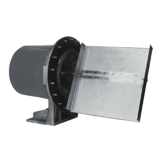
LVDT Moving Beam travel Sensing Plate Impact force The ILE-37 sensing head is used with Milltronics E-40 (general purpose), C-40 (coal scale), A-40 (aerated gravity conveyor), and V-40 (vertical material drop) dry solids flowmeters. E-40 A-40 C-40 Page 2 ILE-37 Sensing Head –... -
Page 5: Specifications
• 0.2% Construction • dust-tight cast aluminum frame with fiberglass rear cover M ounting • side mount or base mount (to suit application) Sensor Type • LVDT (linear variable differential transformer) 7ML19981CW01 ILE-37 Sensing Head – INSTRUCTION MANUAL Page 3... - Page 6 • UHMW polyurethane or Ceramic Tile lining • Teflon or plasma coating LVDT Conditioner Card Pow er • ± 5Vdc (typically from an Accumass Integrator) Ambient Temperature • –40 to 50 C (–40 to 122 Page 4 ILE-37 Sensing Head – INSTRUCTION MANUAL 7ML19981CW01...
- Page 7 For connection betw een LVDT and remote LVDT Conditioner Card, or directly betw een LVDT and Integrator • Belden 8404, 4 conductor, shielded 20 AWG or equivalent, 300 m (1000 ft) maximum 7ML19981CW01 ILE-37 Sensing Head – INSTRUCTION MANUAL Page 5...
-
Page 8: Installation
With the flowmeter housing installed, remove the ILE-37 sensing head cover. Loosen the four ILE-37 mounting bolts. Place a spirit level on the flat top of the ILE-37 frame: adjust the sensing head level by rotating it, and retighten the mounting bolts. -
Page 9: Base Mount
Base M ount With the flowmeter housing installed, mount the ILE-37 to a rigid support structure. With the outer gasket in place, bolt the ILE-37 to the housing. Adjust the sensing head levelling hardware provided, to establish level in both horizontal planes. -
Page 10: Viscous Damper
LVDT Sensing Head Terminal Cable Block Clamp – – To Integrator *For Encapsulated LVDT (hazardous) YEL = WHITE BLU = ORANGE GRN = YELLOW Note: Ground shield at Integrator only. Page 8 ILE-37 Sensing Head – INSTRUCTION MANUAL 7ML19981CW01... -
Page 11: Non-Hazardous Unit With Sensing Head Mounted Lvdt Conditioner Card
Non-Hazardous Unit w ith Sensing Head M ounted LVDT Conditioner Card • Not applicable to Hazardous-rated units • LVDT to LVDT Conditioner Card connections are made by Milltronics LVDT Milltronics LVDT Conditioner Card LVDT INTEGRATOR 14 1 BLUE YELLOW BLACK... -
Page 12: Non-Hazardous Unit With Remote-Located Lvdt Conditioner Card
Run additional conductors: - from SF500 terminal 12 to conditioner terminal block marked "Integrator +EXC" - from SF500 terminal 13 to conditioner terminal block marked "Integrator –EXC" For further connection information on specific LVDTs, consult Milltronics. ♦ Note: Shields are common, but not grounded to chassis. Run cable shields through SHLD terminals and ground at Integrator only. -
Page 13: Calibration
To Integrator LVDT EXC. Increase Decrease or LVDT Conditioner Card Note: Ensure the new position of the LVDT core allows free movement within the LVDT bore. Use 80 grams for A-40 flowmeters. 7ML19981CW01 ILE-37 Sensing Head – INSTRUCTION MANUAL Page 11... -
Page 14: Span Test
The LVDT core must not contact the inside of the LVDT over the range of core travel. • The actual LVDT core travel during this procedure is less than 3 mm (1/8"). 0.050 0.015 0.750 0.150 0.500 1.000 Page 12 ILE-37 Sensing Head – INSTRUCTION MANUAL 7ML19981CW01... -
Page 15: Sensing Head Level Test
Zero and Span calibration, Span Adjust, and Factoring, should be performed. Sensing Changes < 0.01 Vac Plate Voltmeter Test Weight 7ML19981CW01 ILE-37 Sensing Head – INSTRUCTION MANUAL Page 13... -
Page 16: Integrator Calibration
Accurate calibration is not assured until material tests and a Manual Span Adjustment have been performed, as outlined in the Integrator Instruction Manual. String Fixing Bolt Calibration Pulley String Test Weight Page 14 ILE-37 Sensing Head – INSTRUCTION MANUAL 7ML19981CW01... -
Page 17: M Aintenance And Spare Parts
(base mount version only) • damping fluid • sensing plate Contact Milltronics or your distributor for spare parts ordering information. The Siemens Milltronics Web site is: www.milltronics.com 7ML19981CW01 ILE-37 Sensing Head – INSTRUCTION MANUAL Page 15... -
Page 18: Range Springs
After you have removed and replaced the range spring, recalibrate the flowmeter and integrator. (See the Integrator Manual, CALIBRATION section, for details.) Perform the LVDT output Zero procedure. Perform an integrator Zero and Span calibration. Perform a Span Adjust and Factoring as required. Page 16 ILE-37 Sensing Head – INSTRUCTION MANUAL 7ML19981CW01... -
Page 19: Troubleshooting
Troubleshooting Every Milltronics ILE-37 Sensing Head is subjected to extensive quality assurance procedures to ensure the highest possible degree of quality, reliability, and performance is achieved. The following listing indicates the probable cause, and proper course of action to be taken should the specified fault symptom occur. -
Page 20: Linearity
Some integrators are equipped with a linearization function to compensate for non-linear material flow patterns. Stand-alone linearizing devices are also available for this purpose. Electronic linearization should not be used to correct non-linear test weight results. Page 18 ILE-37 Sensing Head – INSTRUCTION MANUAL 7ML19981CW01... - Page 26 *7ML19981CW01*...
Need help?
Do you have a question about the ILE-37 and is the answer not in the manual?
Questions and answers