Milltronics MiniRanger Plus Instruction Manual
Hide thumbs
Also See for MiniRanger Plus:
- Instruction manual (77 pages) ,
- Instruction manual (58 pages)
Table of Contents
Advertisement
Quick Links
Advertisement
Table of Contents

Related Manuals for Milltronics MiniRanger Plus


Summary of Contents for Milltronics MiniRanger Plus
- Page 1 Instruction Manual March 2005 miniranger PLUS...
- Page 2 The user is responsible for all changes and repairs made to the device by the user or the user’s agent. • All new components are to be provided by Siemens Milltronics Process Instruments Inc. • Restrict repair to faulty components only.
-
Page 3: Table Of Contents
Table of Contents General Information ......................1 About this Manual ...........................1 About MiniRanger Plus ..................... 2 Features ..............................2 Rack and Panel Mount Additional Features ..................2 Specifications ........................3 Installation .......................... 6 Dimensions ...............................6 Mounting ..............................8 Interconnection ............................13 Synchronization .............................14 Communication ............................16 Start Up .......................... - Page 4 Unit Repair and Excluded Liability ....................65 Appendices ........................66 Alphabetical Parameter List .......................66 Programming Chart ..........................67...
-
Page 5: General Information
About this Manual It is essential that this manual be referred to for proper installation and operation of your MiniRanger Plus. As MiniRanger Plus requires an ultrasonic transducer to make a working system, refer to the associated transducer manual as well. -
Page 6: About Miniranger Plus
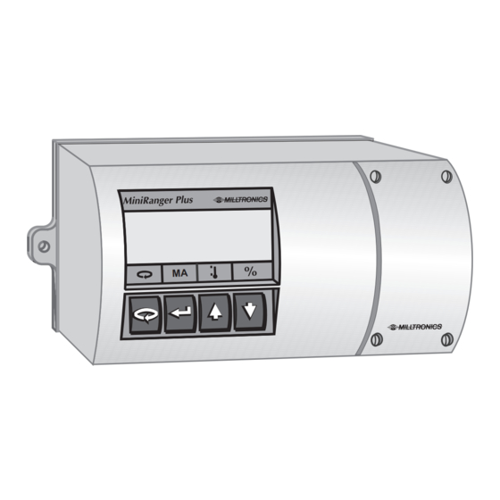
About MiniRanger Plus The MiniRanger Plus is to be used only in the manner outlined in this Note: instruction manual. MiniRanger Plus is a versatile material level monitoring instrument. Material level measurement is achieved using advanced sonic echo ranging techniques. The unit is complete with an integral multifunction liquid crystal display, a four button keypad and an integral junction box. -
Page 7: Specifications
1 form 'C' SPDT contact per relay, rated 5 A at 250 V AC non-inductive • Communication wall / rack / panel specific Approvals • CE , FM, CSA NRTL/C EMC performance available upon request. 7ML19981CJ02 MiniRanger Plus – INSTRUCTION MANUAL Page 3... - Page 8 • installation category: II • pollution degree: 4 Display • 38 x 100 mm (1.5 x 4") multi-field backlit liquid crystal display Communications • Dolphin Plus compatible via optional Siemens Milltronics ComVerter Enclosure • Type 4X/NEMA 4X/IP65 Weight • 1 kg (2.2 lb.)
- Page 9 • Belden 8760, shielded / twisted pair, 18 AWG (0.75mm ) or equivalent • Maximum cable length 10 m (50 ft) RJ-11 Link (Rack & Panel Only): • No shielded cable necessary • Maximum cable length 3 m (10 ft) 7ML19981CJ02 MiniRanger Plus – INSTRUCTION MANUAL Page 5...
-
Page 10: Installation
Wall Mount 270 mm (10.6") 254 mm (10") MiniRanger Plus 138 mm (5.4") 69 mm (2.7") sealed enclosure integral junction box 74 mm (2.9") mount hole 5 mm 6.4 mm (1/4") ∅ (0.2") Page 6 MiniRanger Plus – INSTRUCTION MANUAL 7ML19981CJ02... - Page 11 Rack Mount The MiniRanger Plus rack mount version is a standard DIN 3U/14 HP , 4 rail plug-in unit, for a standard 84 HP deep sub-rack. Panel Mount 72 mm 208 mm (2.9") (8.2") 16 mm (0.6") 144 mm (5.7") 150 mm (5.9")
-
Page 12: Mounting
Relay contact terminals are for use with equipment having no accessible live parts SHIELD and wiring having insulation suitable for at least 250 V. L2/N L1/+ Page 8 MiniRanger Plus – INSTRUCTION MANUAL 7ML19981CJ02... - Page 13 2 row form D female 32 way, per DIN 41612 Push the MiniRanger Plus into the sub-rack until the MiniRanger Plus front cover is snug to the front rails. Tighten the 4 captivated screw to secure the MiniRanger Plus in place.
- Page 14 Terminal Block Layout (Rack Mount) SHLD n.c. Ω n.o. n.c. n.o. L1/+ L2/N All field wiring must have insulation suitable for at least 250V. Warning: Hazardous voltage present on transducer terminals during operation. Page 10 MiniRanger Plus – INSTRUCTION MANUAL 7ML19981CJ02...
- Page 15 Panel Mount Slide the MiniRanger Plus through the panel cut-out. Assemble mounting brackets to the MiniRanger Plus chassis by hooking them into the top and bottom. mounting bracket (top and bottom) cut-out dimension [68 + 0.7 mm] x [138 + 1.0 mm] ([2.68 + 0.03"] x [5.43 + 0.04"])
- Page 16 Terminal Block Layout (Panel Mount) SHLD n.c. Ω n.o. n.c. n.o. L1/+ L2/N All field wiring must have insulation suitable for at least 250V. Warning: Hazardous voltage present on transducer terminals during operation. Page 12 MiniRanger Plus – INSTRUCTION MANUAL 7ML19981CJ02...
-
Page 17: Interconnection
BIC-2, buffered (Siemens Milltronics communications) interface converter * rack and panel only Transducer Wall Mount Rack and Panel Mount to transducer SYNC Refer to transducer instruction manual for location and mounting details. Note: 7ML19981CJ02 MiniRanger Plus – INSTRUCTION MANUAL Page 13... -
Page 18: Synchronization
Synchronization In applications where more than one MiniRanger Plus, to a maximum of 8, are going to be used or where their transducers are sharing a common conduit, synchronization is required. When synchronized, no device transmits within 180 ms of the prior one(s). - Page 19 All relays are certified for use in equipment where the short circuit capacity Note: of the circuits in which they are connected is limited by fuses having ratings not exceeding the rating of the relays. 7ML19981CJ02 MiniRanger Plus – INSTRUCTION MANUAL Page 15...
-
Page 20: Communication
DB-9 connector MiniRanger Plus (Rack and Panel Mount only) 100 Ω ∗ computer serial port DB-25 connector * C20 has 100 Ω internal resistance to ground to avoid ground loops Page 16 MiniRanger Plus – INSTRUCTION MANUAL 7ML19981CJ02... - Page 21 BIC-2 Connection / Bipolar Current MiniRanger Plus Rack and Panel mount BIC-2 PORT 1 board B * C8 is direct to ground typical of BIC-2 ports 1-6 Ground shield at one end only. Note: Power 9-250 V , 40-70 Hz, 38 VA, 12W...
- Page 22 Dolphin Optional Dolphin Interface Wall Mount ComVerter MiniRanger Plus computer RS-232 link via infrared ComVerter Rack and Panel Mount computer RS-232 link direct Refer to Dolphin instruction manual for interconnection details. Note: Page 18 MiniRanger Plus – INSTRUCTION MANUAL 7ML19981CJ02...
-
Page 23: Start Up
Start Up General The MiniRanger Plus has two modes of operation: run and program. When the unit is powered, after installation procedures have been completed, it is programmed to start up in the run mode, to detect the distance from the transducer face to the target in meters. -
Page 24: Display And Keypad
= low, = low-low reading questionable, appears during fail-safe operation auxiliary reading relay status = normal operation =fail-safe operation Keypad access display mA display toggle % program (auxiliary) temperature and units mode (auxiliary) Page 20 MiniRanger Plus – INSTRUCTION MANUAL 7ML19981CJ02... -
Page 25: Program Mode
Rack and Panel Mount parameter type (transducer, relay, or mA output) reading units change value accessed breakpoint accessed Keypad access scroll scroll alternates program run mode down mode between 'select parameter' and 'change value' functions 7ML19981CJ02 MiniRanger Plus – INSTRUCTION MANUAL Page 21... -
Page 26: Setting Up
Programming depicts the wall mount LCD. Display for the rack and panel mount units is the same except for the position of readings and icons. To Access Program : run display program starts at P001 Press To Select a Parameter : Press Page 22 MiniRanger Plus – INSTRUCTION MANUAL 7ML19981CJ02... - Page 27 Press if no response, security not disabled! save and return to 'select parameter' Press function, e.g. P001 = 4 Note: Must be pressed to save change! 7ML19981CJ02 MiniRanger Plus – INSTRUCTION MANUAL Page 23...
- Page 28 P001 Press exit and return to run mode Display Messages ’OPEn' in transducer circuit. Refer to Troubleshooting. ’Short' in transducer circuit or wiring reversed. Refer to Troubleshooting Page 24 MiniRanger Plus – INSTRUCTION MANUAL 7ML19981CJ02...
- Page 29 Express Viewing To view the following readings while in run mode, simultaneously press the depicted keys. Echo Confidence (P805) Echo Strength (P806) Noise (P807) Distance (P923) 7ML19981CJ02 MiniRanger Plus – INSTRUCTION MANUAL Page 25...
-
Page 30: Functional
Functional Transceiver The MiniRanger Plus transceiver operates under 1 of 5 sets of preset conditions (P003), summarized as follows: parameter echo s times long measurement filter response value verification (P070) pulses* 0.1 m/min (slow) • 1 m/min • 10 m/min •... -
Page 31: Sound Velocity
Sound Velocity The MiniRanger Plus can be calibrated to compensate for sound velocity error in fixed temperature, homogenous atmospheres. The basis is to physically measure the level (measuring tape or sight glass) and enter the value via P651. The MiniRanger Plus then calculates the sound velocity by comparing the entered physical measurement to its own ultrasonic measurement. -
Page 32: Loss Of Echo
Loss of Echo A loss of echo occurs when the MiniRanger Plus deems that the calculated measurement is unreliable, i.e. the echo confidence (P805) is less than the threshold (P804). -
Page 33: Relays
Relays General Two onboard relays are provided in the MiniRanger Plus. Each relay can be assigned one of two functions: Alarm or Pump. Relay two can also be used to control a totalizer when the unit is in OCM mode. - Page 34 (PMD). Parameters P001 and P600 must both be set to 1 in order to program the MiniRanger Plus for flow measurement. All nine breakpoints must be used (set with P610 and P611). Zero head is set with P006 and corresponds to zero flow;...
- Page 35 0 = off relay 2 function e.g. 0 = off Press relay 1 on setpoint Press relay 2 on setpoint Press relay 1 off setpoint Press relay 2 off setpoint Press 7ML19981CJ02 MiniRanger Plus – INSTRUCTION MANUAL Page 31...
-
Page 36: Ma Output
* not applicable to high level switch operation, P001 = 4. In such cases, the timer is bypassed and the mode is always 'low'. mA Output The MiniRanger Plus can be programmed to provide an mA output (P200) of 0 - 20 or 4 - 20 mA, and for proportional or inverse span. Programming Upon entering the Program mode, the mA output level holds its prior value. - Page 37 (P001 = 4) 20 mA 0/4 mA 100% 100% *reference value only. mA level limited by near blanking. 0 and 100% are percentage of full scale reading (m, cm, mm, ft, in) 7ML19981CJ02 MiniRanger Plus – INSTRUCTION MANUAL Page 33...
-
Page 38: Run / Program
Run / Program When the MiniRanger Plus changes from run to program, the transceiver stops operating and the last measurement is stored; the associated reading, alarm status, and mA output are held (pump control relays are turned off). As a courtesy, the unit reverts to the parameter last addressed during the previous program session. -
Page 39: Applications
Other applications not described here, such as position monitoring of a piston on a wood pulverizer, are basically improvisational and imaginative ways of applying the MiniRanger Plus. The trick is knowing the parameters available to you, and their limitations. Refer to the Parameter Descriptions that start on 55. -
Page 40: Simple Level Application
A high alarm is required at 4 m from the bottom and a low alarm is required at 1 m from the bottom. The maximum rate of filling or emptying is about 1 m/min. In the event of a loss of echo, the MiniRanger Plus is to go into fail-safe low after 2 min. relay 1... - Page 41 0.1 m deadband) relay 2, off setpoint = 1. 1 m (nominal P113-2 enter ’1.1’ value, 0.1 m deadband) P200 enter ’2’ mA output = 4 - 20 press run to start normal operation 7ML19981CJ02 MiniRanger Plus – INSTRUCTION MANUAL Page 37...
-
Page 42: Pump Control Application
Two pumps are to be controlled by the MiniRanger Plus in lead / lag fashion. The first pump to start at 1 m and the second pump to start at 2 m. Both pumps are to stop at 0.25 m. The maximum estimated filling rate is 1 m/min. - Page 43 0.1 m deadband) relay 2, off setpoint = 0.25 m (nominal P113-2 enter ’ . 25’ value, 0.1 m deadband) P802 enter ’1’ submergence = on press run to start normal operation 7ML19981CJ02 MiniRanger Plus – INSTRUCTION MANUAL Page 39...
-
Page 44: High Level Switch
High Level Switch The MiniRanger Plus can be programmed as a high level switch. Significant differences between this and other modes of operation are: • the fail-safe function (P070 and P071) is effectively disabled • on loss of echo, the measurement immediately defaults to a low value (P006) •... - Page 45 1 P112-1 enter ’1’ relay 1, on setpont = 1 m relay 1, off setpoint = 2 m (nominal P113-1 enter ’2’ value, 1 m deadband) press run to start normal operation 7ML19981CJ02 MiniRanger Plus – INSTRUCTION MANUAL Page 41...
-
Page 46: Applications With Standpipes
In many liquid applications, access to the vessel must be made via a standpipe. In such cases, Siemens Milltronics can provide optional flanged transducers, or split flanges that mate to a flanged standpipe. Another option is to hang the transducer from a blind flange. -
Page 47: Volume Conversion
• an XCT-8 transducer is mounted in a standpipe so that the face is 18 in. above the vessel top. 4.50 ft (P006) 3.00 ft (P007) 12.00 ft 1.5 ft (P053) (P052) 7ML19981CJ02 MiniRanger Plus – INSTRUCTION MANUAL Page 43... - Page 48 P200 mA Range No entry required. (preset to "2" for 4-20 mA output). Now in the RUN mode, the reading value and mA output will represent volume in cubic feet. Page 44 MiniRanger Plus – INSTRUCTION MANUAL 7ML19981CJ02...
-
Page 49: Open Channel Monitoring (Ocm)
Then program the two following parameters to closely match the flow curve of your primary measuring device (PMD). Parameter Description Value P610 (1 .. 9) Head Breakpoints P611 (1 .. 9) Breakpoint Flowrates 7ML19981CJ02 MiniRanger Plus – INSTRUCTION MANUAL Page 45... - Page 50 MiniRanger is in Program mode and the external totalizer will read low. Run the PMD at different head levels and verify the OCM reading given on the MiniRanger to double-check the programming. If this is not possible, double-check the breakpoints for accuracy. Page 46 MiniRanger Plus – INSTRUCTION MANUAL 7ML19981CJ02...
-
Page 51: Parameter Description
Distance(P001 = 3) Level (P001 = 1) Space (P001 = 2) H.L.S. (P001 = 4) P002 Material Optimizes measurement reliability for target type liquids, fluids, or flat surfaces Values irregular surfaces and solids 7ML19981CJ02 MiniRanger Plus – INSTRUCTION MANUAL Page 47... - Page 52 If MiniRanger Plus cannot keep up with the rate of level change, select a faster rate. If the reading bounces around an average value, select a slower rate. In general, reliability is traded for speed.
- Page 53 P050 Tank Shape This parameter, in conjunction with parameters P051, P052 and P053, enable the MiniRanger Plus to show readings based on reservoir volume (rather than level). Volume calculation is an optional feature. MiniRangers with the volume Note: feature have this icon on the front: Enter the Tank Shape value that matches the monitored vessel or reservoir.
- Page 54 Enter the volume of the tank at full (Factory = 1) Notes: • Maximum volume entered not to exceed 30,000. • OCM calculation is an optional feature. MiniRangers with the OCM feature have this icon on the front: Page 50 MiniRanger Plus – INSTRUCTION MANUAL 7ML19981CJ02...
- Page 55 To reference the displayed level to sea level, enter the distance in Units (P005), between Empty (P006) and sea level. (Enter a negative value if Empty is below sea level.) P006 P007 P062 reservoir Range: -999 to 9999 Values Preset: 0.000 7ML19981CJ02 MiniRanger Plus – INSTRUCTION MANUAL Page 51...
- Page 56 P112 Relay A Setpoint The on setpoint in linear units (P005). Refer to page 36. P113 Relay B Setpoint The off setpoint in linear units (P005). Refer to page 36. Page 52 MiniRanger Plus – INSTRUCTION MANUAL 7ML19981CJ02...
- Page 57 The maximum temperature encountered by the integral (transducer) temperature sensor. P341 Run Time View the accumulated number of days the MiniRanger Plus has been operating. P600 Primary Measuring Device The type of primary measuring device (PMD) used for Open Channel Monitoring (OCM).
- Page 58 "click" is reset to 0. This disruption will cause the external totalizer to read lower than the actual OCM total, depending on the number of times programming mode is used and the amount of time spent there. Page 54 MiniRanger Plus – INSTRUCTION MANUAL 7ML19981CJ02...
- Page 59 (P001). • Press (to validate entry). The MiniRanger Plus calculates the new sound velocity for measurement correction. P661 Temp Fixed For use with ST-25 Ultrason® transducers. As these transducers do not have an integral temperature sensor, a nominal value representing the ambient temperature of the transducer must be entered.
- Page 60 Values formatted (commas are inserted between message fields) The MiniRanger Plus Rack and Panel units provide a proprietary 20 mA bipolar current loop for communication with the Siemens Milltronics BIC-2 peripheral device. The MiniRanger Plus uses simplex convention communication protocol. Data messages are continuously transmitted at regular intervals (no poll is required) at 4800 baud.
- Page 61 2 characters, $32 to $FA (convert to decimal and subtract 100, e.g. Temp temperature = 20°C) 5 characters, 00.00 to 9999. (e.g. current level = 85.00% of span, Percent EEEE. = field overflow) End Of Message CR ($0D) 7ML19981CJ02 MiniRanger Plus – INSTRUCTION MANUAL Page 57...
- Page 62 (P070). short minimum echo confidence for short pulse echoes; those within the short pulse echo range. long minimum echo confidence for long pulse echoes. entry: ## : ## (short : long) Page 58 MiniRanger Plus – INSTRUCTION MANUAL 7ML19981CJ02...
- Page 63 This value is preset to 50%. Range: 5 to 95% Values P830 TVT Type Selects the TVT profile applied to the echo profile. standard flat (typically; may yield higher confidences on some solids Values applications) 7ML19981CJ02 MiniRanger Plus – INSTRUCTION MANUAL Page 59...
- Page 64 Siemens Milltronics Not applicable to rack and panel mount units. Note: infrared communication link mirror MiniRanger Plus (wall mount) P910 Relay Tests the alarm relays. de-energizes selected relay Values energizes selected relay Page 60 MiniRanger Plus – INSTRUCTION MANUAL 7ML19981CJ02...
- Page 65 P920 Reading Measurement The reading as viewed in the run mode. Not accessible via application device keypad Note: P999 Master Reset Resets parameters to their factory setting. Press 7ML19981CJ02 MiniRanger Plus – INSTRUCTION MANUAL Page 61...
-
Page 66: Troubleshooting
Try using a longer range trans- ducer Increase fail-safe timer, P070 Clean Move transducer to a better location Material build up on transducer Mount in standpipe face *refer to associated transducer manual. Page 62 MiniRanger Plus – INSTRUCTION MANUAL 7ML19981CJ02... - Page 67 Reading error progressively Atmosphere other than air or Refer to P651 worsens with distance stratified Screen Blank Loss of Power Check power wiring *refer to associated transducer manual. 7ML19981CJ02 MiniRanger Plus – INSTRUCTION MANUAL Page 63...
- Page 68 High level reading lower than Material is within near blanking Decrease blaking P900 (limit to material level zone transducer minimum range*) or raise transducer. Echo multiple being processed *refer to associated transducer manual. Page 64 MiniRanger Plus – INSTRUCTION MANUAL 7ML19981CJ02...
-
Page 69: Maintenance
The MiniRanger Plus requires no maintenance. However, a program of periodic checks is advised. If the MiniRanger Plus wall unit is mounted in a dusty or oily environment, make sure that the programmer, optional Dolphin ComVerter, and front cover are kept clean using a vacuum cleaner and a clean dry brush;... -
Page 70: Appendices
P004 memory P901 TVT type P830 near blanking P800 units P005 noise P807 offset calibration P650 offset reading P062 operation P001 peripheral communication P740 primary measuring device P600 programmer interface P907 Page 66 MiniRanger Plus – INSTRUCTION MANUAL 7ML19981CJ02... -
Page 71: Programming Chart
P661 Teamperature, Fixed P740 Peripheral Communication* P800 Near Blanking P801 Range Extension P802 Submergence Transducer P804 Confidence Treshold P820 Algorithm P825 Echo Marker Trigger P830 TVT Type *rack and panel mounts only 7ML19981CJ02 MiniRanger Plus – INSTRUCTION MANUAL Page 67... - Page 72 Siemens Milltronics Process Instruments Inc. Siemens Milltronics Process Instruments Inc. 2005 1954Technology Drive, P .O. Box 4225 Subject to change without prior notice Peterborough, ON, Canada K9J 7B1 Rev. 2.0 Tel: (705) 745-2431 Fax: (705) 741-0466 *7ml19981cj02* Email: techpubs.smpi@siemens.com...
Need help?
Do you have a question about the MiniRanger Plus and is the answer not in the manual?
Questions and answers