
Subscribe to Our Youtube Channel
Related Manuals for Rice Lake 120 Plus


Summary of Contents for Rice Lake 120 Plus
- Page 1 120 Plus Digital Weight Indicator Software Version 5.00 Technical Manual PN 105914 Rev B...
-
Page 3: Table Of Contents
Course descriptions and dates can be viewed at www.ricelake.com/training or obtained by calling 715-234-9171 and asking for the training department. © Rice Lake Weighing Systems. All rights reserved. Printed in the United States of America. Specifications subject to change without notice. - Page 4 8.8 120 Plus Specifications ........
-
Page 5: Introduction
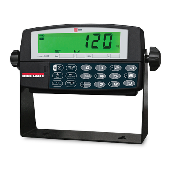
Overview The 120 Plus weight indicator is a precision digital weight indicator that takes portability to a new level. The feature of running on a rechargeable battery pack allows the 120 Plus to operate anywhere. The indicator front panel consists of a backlit, six-digit, 7-segment LCD display and a set of keys. The prominent features of the 120 Plus include: •... -
Page 6: Safety
Do not operate or work on this equipment unless you have read and understand the instructions and warnings in this manual. Failure to follow the instructions or heed the warnings could result in injury or death. Contact any Rice Lake Weighing Systems dealer for replacement manuals. Proper care is your responsibility. -
Page 7: Operating Modes
Operating Modes The 120 Plus supports the following modes of operation: Mode Description Normal mode Also known as the weighing mode. The display shows measured weights in the units required. See Section 1.5 for more information. Setup (configuration) Configuration mode allows user to modify parameter values and calibrate the indicator. See mode Section 3.0 for more information. -
Page 8: Lcd Annunciators
LCD Annunciators The 120 Plus display uses a set of LCD annunciators to provide additional information about the value being displayed. Figure 1-2. 120 Plus LCD Annunciators The following table displays the functions of the LCD annunciators Number Name Function Battery Level icon indicates the level of the battery. -
Page 9: Rear View
Rear View Figure 1-3 shows the rear view of the 120 Plus. COVI COVI COVI Load Cell Load Cell Load Cell Power Communication Load Cell and IO Port Figure 1-3. Rear View of the 120 Plus Indicator Setup Switch Figure 1-4 shows the location of the setup switch. -
Page 10: Indicator Operations
2. Enter a number. If a number is not entered within five seconds, the 120 Plus returns to normal weighing mode. 3. After entering the number, the 120 Plus will recall the preset tare, display it for two seconds, and switch to mode using the recalled value. - Page 11 1.8.9 Hold Display There are four modes for the hold function, see Section 3.5 on page 22. Toggle Hold Mode 1. Wait for the standstill annunciator ( ). The wait time will depend on the setting of the motion band parameter.
-
Page 12: Installation
The indicator must be installed near an ZERO easily accessible power source or can be operated on an internal battery. The various sockets on the 120 Plus are shown in Figure 2-1. Load Cell Figure 2-1. 120 Plus Cable Connections Power Connector The following table details the power connector pin functions. -
Page 13: Optional Digital I/O-Interface Cable (Pn 106705)
2.2.1 Optional Digital I/O-Interface Cable (PN 106705) An optional 15 pin digital I/O-interface cable plugs into the back of the 120 Plus indicator via the DB-15 connector. Figure 2-3. Optional Digital I/O-Interface Connector The blunt end of wires are delivered with approximately four inches of exposed wire that can typically be wired into terminal strips or connectors. -
Page 14: Optional I/O Connections
2.4.1 Remote Switcher The 120 Plus indicator has provisions to connect an external input device such as a push button switch (purchased separately) to provide a keypad function. The keypad function can be set in the SETPNT menu; the external device must provide a normally open (N.O.) momentary switch contact. -
Page 15: Setpoints Output
2.4.2 Setpoints Output Output drivers for the 120 Plus are isolated open emitter transistor drives that are capable of driving up to a total of 800mA. This configuration allows for the direct connection of the 120 Plus outputs to most types of PLC. -
Page 16: Battery Installation
Lake Weighing Systems original batteries (PN 103637). The warranty does not cover damage caused by using non- Rice Lake batteries and/or chargers. • New batteries or batteries stored for a long time may take more time to charge. When charging your battery, keep it near room temperature. -
Page 17: Configuration
Serial Number Displays the serial number of the indicator Table 3-1. 120 Plus Menu Structure The front panel keys can be used as directional keys to navigate through the menus in configuration mode. An example of navigation process is shown below in Figure 3-2. -
Page 18: Configuration Menu
THRESHOLD RANGE MODE 8OUT NONE NTEP Enable 2OUT OMIL Disable 4OUT 20 % CANADA 10DD 16OUT 50 % NONE 20DD 32OUT 100 % 64OUT 50DD 128OUT 100DD 200DD 250DD Figure 3-3. Configuration Menu 120 Plus Digital Weight Indicator Technical Manual... - Page 19 The following table describes the various configuration options (values in bold are the default values). Parameter Options Description Graduations 10000 The value entered must be in the range 1 ~ 100000 and should be consistent with legal Number requirements and environmental limits on system resolution. To calculate GRADS, use the formula: Grads = Capacity / Minimum Weight (or division size) Minimum Weight for primary and secondary units are specified in the FORMAT menu.
-
Page 20: Format Menu
DECIMAL POINT UNITS DECIMAL POINT UNITS 250MS DIVISIONS DIVISIONS 500MS 1SEC 2SEC 888888 88888.8 8.88888 888888 88.8888 8.88888 888.888 88.8888 8888.88 888.888 88888.8 8888.88 100D 100D 200D 200D 500D 500D Figure 3-4. Format Menu 120 Plus Digital Weight Indicator Technical Manual... - Page 21 Parameter Options Description Primary DECPNT Specifies the Primary decimal position, display divisions, and units used for DSPDIV the primary units. UNIT Decimal point 888888 Decimal Point defines the location of the decimal point. The value set 8.88888 should be consistent with local legal requirements. 88.8888 888.888 8888.88...
-
Page 22: Calibration
To WVAL edit the value, press the Enter key; the last digit of the displayed value blinks. Press the key to clear clear 120 Plus Digital Weight Indicator Technical Manual... -
Page 23: Edp Command Calibration
the value, then use the numeric keys (0-9) to enter the test weight value. Press the key to save the test enter weight value and navigate to span calibration ( WSPAN 5. With displayed, press the key to calibrate span. The indicator displays while calibration WSPAN enter... -
Page 24: Serial Menu
Baud Rate. Selects the transmission speed for the EDP port. 1200 2400 4800 19200 38400 Bits 8NONE Selects number of data bits and parity of data transmitted from the EDP port. 7ODD 7EVEN 7SPACE Table 3-5. Serial Menu 120 Plus Digital Weight Indicator Technical Manual... - Page 25 Print destination. Selects the port for data transmission when the PRINT key is pressed or the KPRINT EDP command is sent. Stream Selects the serial port used for continuous transmission. See " Continuous Output (Stream) Format" on page 46 for more information about the 120 Plus continuous data format. Stream Delay 250MS...
-
Page 26: Program Menu
Enables or disables the audible tones when the keys are pressed. Consecutive Consecutive Numbering allows sequential numbering for print operations. This value is Numbering number increased following each print operation. Table 3-6. Program Menu 120 Plus Digital Weight Indicator Technical Manual... - Page 27 Parameter Options Description Gravity Adjust Turns the gravity correction on or off. This can be used along with the Latitude and Elevation parameters of the Calibration menu to compensate for the varience in gravitational pull from one location to another. See Section 8.6 for more information. Hold MD Toggle Hold function...
-
Page 28: Print Format Menu
DELETE NONE Deletes the last character of the value edited by the previous EDIT option. This shifts all data after it to the left by one position. Table 3-7. Print Format Options 120 Plus Digital Weight Indicator Technical Manual... -
Page 29: Set Points Menu
Set Points Menu Use this menu to configure set points settings. The Set Points menu is shown below: SET POINTS SET POINT 1 KIND CONTACT CONDITION WEIGHT VALUE TIMER DELAY HYSTERESIS BUZZER N.CLOSE NORMAL NONE NONE GROSS N.OPEN STABLE number 250MS 250MS 500MS... - Page 30 Set Point 2 Specifies settings for mode, contact type, condition, weight valve, timer, delay, and KIND hysteresis used by the set point 2. CONTACT CONDIT WVAL TIMER DELAY HYSTER BUZZER Table 3-8. Setpoints Menu 120 Plus Digital Weight Indicator Technical Manual...
-
Page 31: Time Menu
Parameter Options Description Remote Switch OF.OF.OF Specifies the function activated by remote switch inputs 1, 2 and 3. PR.TA.ZO OF.OF.OF disable all remote switches UN.TA.ZO PR.TA.ZO provides the same functions as the front panel keys. Remote switch 1 be ZERO key Remote switch 2 be TARE key Remote switch 3 be Print/Enter key UN.TA.ZO provides the same functions as the front panel keys. -
Page 32: Date Menu
The VERS menu is used to check the software version, model name and serial number installed in the indicator. There are no parameters associated with the Version menu; when selected, the indicator displays the installed. VERS MODEL S oftware Model Serial V ersion Number Number Figure 3-13. Version Menu 120 Plus Digital Weight Indicator Technical Manual... -
Page 33: Test Mode Operations
Test Mode Operations Use this mode to test the parameters of the weight indicator. This procedure should only be performed by a certified technician. To enter test mode, press the for three seconds. The display will change from setup switch CONFIG to A/DTST TEST LCD DEFAULT... - Page 34 This displays the value received from serial port on the front panel. The format of the data displayed by the ECHO R command is shown as shown: Received character order Blank Visible ASCII Char ASCII in HEX code Table 4-1. Test Mode Option Parameters 120 Plus Digital Weight Indicator Technical Manual...
-
Page 35: Panel Mode Operations
Panel Mode Operations Panel Mode provides access to setting the serial port, non-meteorological parameters, time, date, consecutive number, print format, set points, and test items without the need to press the Setup Switch To enter Panel Mode, press and hold the key under normal mode until the menu is displayed. - Page 36 Sets the date. See Section 3.9 on page 28 for more information. YEAR MONTH DATFRM VERSION Displays the installed software version. MODEL Displays the model number. SERIAL Displays the serial number of the unit. NUMBER Table 5-1. Panel Mode Description 120 Plus Digital Weight Indicator Technical Manual...
-
Page 37: Print Formatting
Write the print format data in pure text format. The following samples are for an Eltron LP 2742 printer. Wwpf = 0 A0,0,0,3,1,2,N,"Rice Lake Weighing Systems. @d @t @C" A8,50,0,5,1,1,N,"@G" @MA8,120,0,5,1,1,N,"@T" A8,190,0,5,1,1,N,"@N"@M B8,260,0,3,3,7,100,B,"@G" First, place a "WWPF=0" in the first line to indicate that the following is a print format file. Place printer parameters in the beginning of each line as required, and then use double quotes to contain the text that you want to print on the ticket (see table above). - Page 38 EDP interface of the 120 Plus. • Some characters cannot be displayed on the 120 Plus front panel (See the ASCII character chart in Appendix C - ASCII Set and Specifications and Appendix E - Front Panel Display Characters on pages 44 and 48.) and are shown as blanks.
- Page 39 Continuous Output Continuous Output (Stream) Format All values are ASCII code characters. <STX> <POL> <wwwwwww> <UNIT> <G/N> <S> <EXTEND 1> <TERM> ASCII 02 G = Gross Extend 1 format <CR> <LF> decimal N = Net or <CR> see below ASCII 13, 10 decimal Polarity: L = pounds Status:...
-
Page 40: Appendix
If an unknown command is sent, or a known command is sent, but an attempt is made to set it to an incorrect value, the indicator will respond with the value as set by the WHAT parameter, either ?? (default) or ?. 120 Plus Digital Weight Indicator Technical Manual... -
Page 41: General Commands
8.1.1 General Commands Command Function DUMPALL List all parameter values VERSION Return the firmware version, checksum, and serial number in the following format: 120PLS v.vv_ccccc SN: sssss where v.vv is the version, cccccc is the checksum and ssssss is the serial number. -
Page 42: Format Commands
Stream additional information with raw data and time ON, OFF STMSTA Stream additional information with weight status ON, OFF MONBAT Stream additional information with battery data ON, OFF WHAT Defines response to invalid command ??, ? Table 8-5. Serial Commands 120 Plus Digital Weight Indicator Technical Manual... -
Page 43: Program Commands
8.1.6 Program Commands Command Description Values PWRUPMD Power up mode GO, DELAY RPNBAND Return to zero point band 10D, OFF, 1D, 2D, 3D, 5D,20D, 50D SHUTDN Power shut down mode None, 1 min, 2 min, 5 min, 10 min BAKLIT Back light of LCD OFF, 15 sec, 30 sec, 1 min, ON BUZZER... -
Page 44: Key Press On Edp Commands
Same function as ENTER key press KPTARE Same function as PRESET TARE key press KCLEAR Same function as CLEAR key press KNR0-9 Same function as 0-9 key press Table 8-9. Key Press Commands 120 Plus Digital Weight Indicator Technical Manual... -
Page 45: Tare, Zero Key And Regulat Parameter
8.1.10 Tare, Zero key and REGULAT Parameter The function of the keys depends on the value specified for the parameter. Table 8-11 TARE ZERO REGULAT below describes the function of these keys for each of the regulatory modes. Key press function REGULAT parameter value Weight on scale... -
Page 46: Ascii Set And Specifications
Plus PFORMT menu. The actual character printed depends on the character mapping used by the output device. The 120 Plus can send and receive any ASCII character value (decimal 0-255) but the indicator display is limited to numbers, upper- case, unaccented letters, and a few special characters. - Page 47 ASCII ASCII ASCII ASCII Ç á ü í é ó â ú ä ñ à Ñ å ª ç º ê ¿ ë è ¬ ï î ...
-
Page 48: Error Messages
Error Messages The 120 Plus indicator displays a number of error messages. When an error occurs, the message is shown on the indicator LED display. Error Message Description Solution CENTER Gross > Overload limit Gross value exceeds overload limit. Check configuration or DASHES signal input level. -
Page 49: Gravity Compensation
This feature is used to compensate for the variance in gravitational pull from one location to another and is available for the 120 Plus. To calibrate with gravity compensation, the GRAVADJ parameter must be set to ON, and the LATITD (latitude in degree) and ELEVTN (elevation in meters, relative to sea level) parameters set before calibrating the 120 Plus. -
Page 50: Plus Specifications
Voltage: 5VDC, using power adapter 115 or 230VAC Power Consumption: 11W in-charger, 2W off- charger Battery Operation: Charge Time: 7 ~ 10 hours Estimated Battery Life: Full active: 46 ~ 63 hours Saving: 300 hours 120 Plus Digital Weight Indicator Technical Manual... -
Page 51: 120 Plus Limited Warranty
120 Plus Limited Warranty Rice Lake Weighing Systems (RLWS) warrants that all RLWS equipment and systems properly installed by a Distributor or Original Equipment Manufacturer (OEM) will operate per written specifications as confirmed by the Distributor/OEM and accepted by RLWS. All systems and components are warranted against defects in materials and workmanship for one year. - Page 52 120 Plus Digital Weight Indicator Technical Manual...
- Page 54 230 W. Coleman St. • Rice Lake, WI 54868 • USA U.S. 800-472-6703 • Canada/Mexico 800-321-6703 • International 715-234-9171 • Europe +31 (0)26 472 1319 www.ricelake.com www.ricelake.mx www.ricelake.eu www.ricelake.co.in m.ricelake.com © Rice Lake Weighing Systems 05/13/2015 PN 105914 Rev B...
Need help?
Do you have a question about the 120 Plus and is the answer not in the manual?
Questions and answers