Table of Contents
Advertisement
Advertisement
Table of Contents

Subscribe to Our Youtube Channel
Related Manuals for Max BC-RT-TRX-CyG-4


Summary of Contents for Max BC-RT-TRX-CyG-4
- Page 1 Radiator Thermostat BC-RT-TRX-CyG-4...
- Page 2 Scope of delivery Scope of delivery Quan- Item tity MAX! Radiator Thermostat + Danfoss RA adapter Danfoss RAV adapter Danfoss RAV tappet extension Danfoss RAVL adapter Cylinder head screw M4 x 12 mm, nut M4 Support ring LR6/mignon/AA battery Brief instruction in German/English, French/Dutch and Polish/Italian...
-
Page 3: Table Of Contents
Table of contents Table of contents Information about this manual ......... 4 Safety instructions ............ 4 Function ..............5 Device overview ............7 Start-up ..............8 Teaching-in ............. 19 Operating modes (Auto/manu/holiday) ....23 Comfort and reduction temperature ...... 24 Setting the holiday function ........ -
Page 4: Information About This Manual
Information about this manual nformatIon about thIs manual Read this manual carefully before starting to use the device. Keep the manual so you can refer to it at a later date if you need to. If you hand over the device to other persons for use, please hand over the operating manual as well. -
Page 5: Function
Function Using the device for any purpose other than that de- scribed in this operating manual does not fall within the scope of intended use and shall invalidate any warranty or liability. This also applies to any conver- sion or modification work. The device is intended for private use only. - Page 6 Function MAX! Room solution In the room solution, the settings of all connected devices in your room can comfortably be made via the MAX! Wall Thermostat+. Up to 8 MAX! Radiator Thermostats + and 8 MAX! Window Sensors can be connected and controlled via the MAX! Wall Thermo- stat + .
-
Page 7: Device Overview
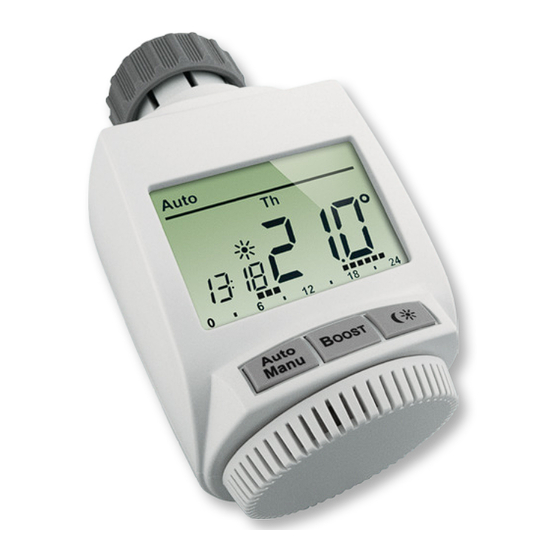
Device overview evIce overvIew Automatic mode (Auto), manual mode (Manu), holiday mode ), Boost function ( ), open-window function ( ), oper- ating lock ( ) Weekday, replace batteries of the Radiator Thermostat + ( ), re- place batteries of a taught-in device (e.g. window sensor) ), radio activity ( ), comfort/reduction temperature ( time/date, activity symbol ( ) Bar chart of programmed heating phases of current day... -
Page 8: Start-Up
Start-up Isplay content In normal moDe Operating mode, week day, setpoint temperature, time, ra- dio signal and switching time periods are displayed in nor- mal mode. In the example, the MAX! Radiator Thermostat+ is in automatic mode (Auto) and the comfort temperature ) of 21.0°C is set. - Page 9 Start-up • Remove the battery compartment cover by pushing it forwards. • Insert 2 LR06/mignon/AA batteries in the battery compart- ment, making sure they are the right way round. • Reattach the battery compartment cover and latch it into place. After inserting batteries, the radiator thermostat has to be mounted on the radiator (see sec.
- Page 10 Start-up et Date anD tIme If batteries are inserted or replaced, the date and time is automatically requested after a brief display of the firm- ware version number: • Set the year, month, day, hour and minute with the hand- wheel and confirm with the Boost button.
- Page 11 Start-up turers such as • Heimeier • MNG • Junkers • Landis&Gyr (Duodyr) • Honeywell-Braukmann • Oventrop • Schlösser • Comap • Valf Sanayii • Mertik Maxitrol • Watts • Wingenroth (Wiroflex) • R.B.M • Tiemme • Jaga • Siemens •...
- Page 12 Start-up • Union nut: Unscrew the union nut in an anticlockwise di- rection (2). The thermostat head can then be removed (3). • Snap-on fastenings: Thermostat dials that have been at- tached using this method can be easily released by giving the lock/union nut a slight turn in the anticlockwise di- rection (2).
- Page 13 Start-up 5.3.2 Adapter for Danfoss One of the provided adapters is needed to attach to Danfoss valves. The assignment of the suitable adapter ring to the relevant valve can be found in the following illustrations. Please ensure that you do not trap your fingers be- tween the two halves of the adapter! The Danfoss valve bodies have elongated notches (I) around their circumference (see arrow), which also ensure that the...
- Page 14 Start-up During installation, please ensure that the pins inside the adapter (J) are lined up with the notches (I) on the valve.
- Page 15 Start-up Ensure that a suitable adapter for the valve is properly clipped on. The lifter extension (K) must be fitted to the valve pin of RAV valves prior to installation. During installation, please ensure that the pins inside the adapter (J) are lined up with the notches (I) on the valve.
- Page 16 Start-up The adapter RAVL does not have to be screwed.
- Page 17 Start-up 5.3.3 Support ring The valves from different manufacturers may have tolerance fluctuations that make the radiator thermostat more loosely seated on the valve. In this case, the provided support ring (L) should be placed into the flange before mounting the ra- diator thermostat.
- Page 18 Start-up DaptIng run Once the batteries have been inserted and date and time have been set, the motor reverses; meanwhile, "InS" and the ac- tivity symbol ( ) are displayed. As soon as "InS" is displayed ), the radiator thermostat + without the activity symbol ( can be mounted.
-
Page 19: Teaching-In
Teaching-in eachIng In order to be able to use the MAX! Radiator Thermostat + in your installation, you must teach it in first. The teach-in procedure depends on the system variant used. Choose your system variant (House, Room or Radiator solution) and fol- low the instructions below. - Page 20 Teaching-in > 3 s • After teaching-in has been successful, the display returns back to normal display. As soon as the MAX! Radiator Thermostat + has been taught-in to a MAX! Cube, all settings will be trans- mitted via radio. The MAX! Radiator Thermostat + can only be taught- in to one MAX! Cube.
- Page 21 Teaching-in the MAX! Wall Thermostat + . To teaching-in the device to the MAX! Wall Thermostat + , proceed as follows: • Press and hold down the OK button of the MAX! Wall Ther- mostat + for at least 3 seconds to activate teach-in mode (1). •...
- Page 22 Teaching-in MAX! Radiator solution In the MAX! Room solution all settings and program- mings (e.g. week programs) can be made directly via the MAX! Radiator Thermostat + . All devices have to be taught-in to each other, i.e. is all MAX! Radiator Thermostats + and all MAX! Window Sensors have to be taught-in to each other (max.
-
Page 23: Operating Modes (Auto/Manu/Holiday)
Operating modes (Auto/manu/holiday) • Activate the teach-in mode of your MAX! Radiator Thermo- stat + . Press and hold down the Boost button for at least 3 seconds. The display shows the remaining teach-in time in seconds. The teach-in time is 30 seconds. >... -
Page 24: Comfort And Reduction Temperature
Comfort and reduction temperature in accordance with the time profile saved (heat/reduce). • Manu: Manual operation - the manually set temperature using the handwheel is maintained permanently. • Holiday ( ): In holiday mode, the set temperature is maintained up to an end time, at which point the device switches to auto mode automatically. -
Page 25: Setting The Holiday Function
Setting the holiday function • Press and hold the comfort/reduction temperate button ) for at least 3 seconds. • The display shows the symbol ( ) and the comfort tem- perature as defined. • Change the temperature with the handwheel and confirm with the Boost button. -
Page 26: Configuration Menu
Configuration menu If you use the MAX! Radiator Thermostat + in the MAX! Radiator solution, proceed as follows: • Briefly press the Auto/Manu button repeatedly, until the suitcase symbol ( ) appears in the display. • Set the time via the handwheel up to which the temperature is to be maintained and then confirm with the Boost button. - Page 27 Configuration menu MAX! Radiator solution Settings of the MAX! Radiator Thermostat + can be changed in the configuration menu of the device. The menu can be accessed by pressing the Auto/Mode button for more than 3 seconds. Menu items can be selected with the handwheel and confirmed with the Boost button.
- Page 28 Configuration menu 14.8 tOF: Set temperature offset 14.9 UnL: Teach-out wireless components 14.10 rES: Restoring the factory settings 10.1 s ettIng the week program In the week program, for each weekday up to 6 heating phas- es (13 change settings) can be set separately. The program- ming is carried out for the days chosen, whereby tempera- ture settings have to be set for the entire period between 00:00 and 23:59.
- Page 29 Configuration menu • Confirm with the Boost button. • Now set the end time of the first time period (example: 6:00 h for the period 0:00 – 6:00 h). • Confirm with the Boost button. • With the handwheel select the chosen temperature for the previously chosen time period (example: 17.0°C).
- Page 30 Configuration menu from 00:00 to 06:00 17.0 °C from 06:00 to 09:00 21.0 °C from 09:00 to 17:00 17.0 °C from 17:00 to 23:00 21.0 °C from 23:00 to 23:59 17.0 °C The display will show bars for those heating phases where the set temperature for the period is higher than the saved reduction temperature.
- Page 31 Configuration menu 10.2 hangIng Date anD tIme In the configuration menu, date and time can be adjusted. In the MAX! House solution you can configure the set- tings for the MAX! Radiator Thermostat + via the MAX! software. In the MAX! Room solution you can configure the set- tings for the MAX! Radiator Thermostat+ via the MAX! Wall Thermostat + .
- Page 32 Configuration menu Activate boost function: • Press the Boost button to activate the boost function. • The remaining time for the function is counted down in seconds ("300" to "000"). Whilst the function is active, is displayed. • The activity symbol ( ) is displayed as long as the adjust- ing pin opens/closes the valve.
- Page 33 Configuration menu • Set the valve opening (in percentage) with the handwheel and confirm with the Boost button. The radiant heat will not have an immediate effect if the radiator is covered or concealed (e.g. by a sofa). If the duration of the boost function is set so that the display exceeds 999 seconds, the display value switches from seconds to minutes.
- Page 34 Configuration menu value. When the MAX! Window Sensor detects the closing of the window, all MAX! Radiator Thermostats installed in the room are immediately reset to their original mode. Adjust reduced temperature and duration: A reduced temperature of 12° C and a duration of 15 minutes is set as default.
- Page 35 Configuration menu When a MAX! Window Sensor is taught-in, the MAX! Radiator Thermostat+ does not react to a temperature fall. 10.5 s ettIng routIne DescalIng The MAX! Radiator Thermostat + can protect against valve calcification automatically. Therefore, an automatic routine descaling is performed once a week.
- Page 36 Configuration menu “CAL” is displayed during descaling. 10.6 s wItchIng tIme Date DIsplay The factory setting will show the time on the display. In the menu the display can be switched to the date. In the MAX! House solution you can configure the set- tings for the MAX! Radiator Thermostat + via the MAX! software.
- Page 37 Configuration menu In the MAX! House solution you can configure the set- tings for the MAX! Radiator Thermostat + via the MAX! software. In the MAX! Room solution you can configure the set- tings for the MAX! Radiator Thermostat+ via the MAX! Wall Thermostat + .
- Page 38 Configuration menu In the MAX! House solution you can configure the set- tings for the MAX! Radiator Thermostat + via the MAX! software. In the MAX! Room solution you can configure the set- tings for the MAX! Radiator Thermostat+ via the MAX! Wall Thermostat + .
- Page 39 Configuration menu If you use the MAX! Radiator Thermostat + in the MAX! Radiator solution, proceed as follows: • Press the Auto/Manu button longer than 3 seconds. • Select the menu item „UnL“ with the handwheel and con- firm with the Boost button. •...
-
Page 40: Child Safeguard/Operating Lock
Child safeguard/operating lock • „ACC“ appears in the display. Confirm with the Boost but- ton to reset the device. If you have taught-in several MAX! Radiator Thermo- stats or MAX! Window Sensors, all devices have to be reset. hIlD safeguarD operatIng lock Basic child safeguard/operating lock Operation of the device can be locked to avoid settings be-... - Page 41 Child safeguard/operating lock ( ). The adjustable temperature range is also restricted. The minimum and maximum temperature upper limits are be- tween 5.0 °C and 24.0 °C. The advanced operating lock is deactivated in the initial state. Activating the operating lock: •...
- Page 42 Child safeguard/operating lock ton to confirm the correct digits. • After you have selected the correct code, "ON" or "OFF" is displayed. Select "OFF" with the handwheel and press the Boost button to confirm. • The display returns to normal. The -symbol is off and the advanced operating lock is deactivated.
-
Page 43: Activate Heating Pause (Battery Saving)
Activate heating pause (battery saving) performing a factory reset or via the MAX! Cube (see sec. „13 Restore factory settings“ on page 44). The code can only be changed on the device itself and not via the local MAX! software. ctIvate heatIng pause battery savIng Battery life can be prolonged by switching the heating off in... -
Page 44: Restore Factory Settings
Restore factory settings 12.1 a ctIvatIng frost protectIon operatIon raDIator swItcheD off If the room does not need to be heated, the valve can be closed. The valve is only opened if there is a risk of frost. The calcification protection continues to run. In the MAX! House solution you can configure the set- tings for the MAX! Radiator Thermostat + via the MAX! software. -
Page 45: Led Flashing Sequences And Transmission Behaviour
LED flashing sequences and transmission behaviour Before restoring the factory settings of the MAX! Ra- diator Thermostat + , first delete the device from the local MAX! software if you use the radiator thermo- stat in connection with a MAX! Cube. •... -
Page 46: Maintenance And Cleaning
Maintenance and cleaning Temperature Device defective - please contact sensor defective your specialist dealer. Battery voltage Replace the batteries of the too low, valve radiator thermostat moved to error position Slowly Connection to Check the power supply and flashing taught-in MAX! the batteries of taught-in MAX! antenna components lost... -
Page 47: Information About Radio Operation
Information about radio operation nformatIon about raDIo operatIon Radio transmission is performed on a non-exclusive trans- mission path, which means that there is a possibility of in- terference occurring. Interference can also be caused by switching operations, electrical motors or defective elec- trical devices. -
Page 48: Technical Specifications
Technical specifications echnIcal specIfIcatIons Device short description: BC-RT-TRX-CyG-4 Supply voltage: 2x 1.5 V LR6/mignon/AA Current consumption: 100 mA (max.) Battery life: 2 years (typ.) Display: Radio frequency: 868.3 MHz Typ. open area RF range: > 100 m Receiver category: SRD category 2 Duty cycle: <... - Page 49 Technical specifications Max. number of devices to be taught-in: MAX! House solution • max. 50 devices in max. 10 rooms, • max. 4 MAX! Eco Switch • per room max. 8 MAX! Radiator Thermostats (+) , 8 MAX! Window Sensors and 1 MAX! Wall Thermostat + MAX! Room solution: •...
- Page 50 Technical specifications Do not dispose of the device with regular domestic waste. Electronic equipment must be disposed of at local collection points for waste electronic equipment in compliance with the Waste Electrical and Electronic Equipment Directive. The CE sign is a free trading sign addressed exclu- sively to the authorities and does not include any warranty of any properties.
- Page 52 Bevollmächtigter des Herstellers: Manufacturer’s authorised representative: eQ-3 AG Maiburger Straße 29 26789 Leer / GERMANY www.eQ-3.de...
Need help?
Do you have a question about the BC-RT-TRX-CyG-4 and is the answer not in the manual?
Questions and answers