
Related Manuals for SMS ControlMate


Summary of Contents for SMS ControlMate
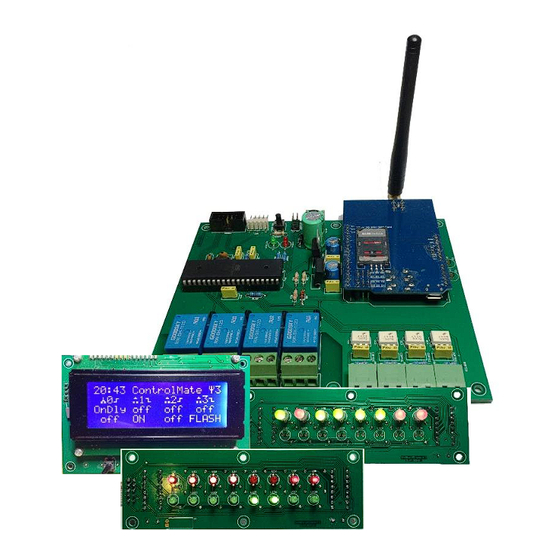
- Page 1 SMS ControlMate Versatile SMS monitoring and control USER GUIDE SMS ControlMate/3G © 2016-2018 info@SL4P.net Page 1 of 56...
-
Page 2: Sms Controlmate/3G
BLANK PAGE SMS ControlMate/3G © 2016-2018 info@SL4P.net Page 2 of 56... -
Page 3: Table Of Contents
MOUNTING DIMENSIONS ......................22 INPUTS & OUTPUTS ........................23 RECOMMENDED ENCLOSURE ...................... 25 POWER & CONTROL CONNECTIONS ..................... 26 USING CONTROLMATE ........................27 POWER-ON ..........................27 GETTING STARTED ........................... 28 SIMPLE CONTROL ........................29 WHO HAS ACCESS TO MY CONTROLLER? ..................31 ONDELay and OFFDELay ...................... - Page 4 During modem registration ...................... 47 During normal operation ......................48 CONSOLE CONNECTIONS ......................... 49 PUTTY TERMINAL CONFIGURATION ..................... 49 TERATERM CONFIGURATION ....................... 50 MODEMS............................51 CONFIGURATION RECORD ....................... 53 CONNECTIVITY WORKSHEET ......................55 SMS ControlMate/3G © 2016-2018 info@SL4P.net Page 4 of 56...
-
Page 5: Introduction
– to re-set or remove the passcode. Applications for ControlMate may be as simple as sensing a gate open or closed, or starting and stopping a generator. Sensing a tank is full, remotely starting a pump, turning on the security lights - and everything between. - Page 6 BLANK PAGE SMS ControlMate/3G © 2016-2018 info@SL4P.net Page 6 of 56...
-
Page 7: Output Relays
If ‘flash’ mode is enabled, the user must ensure the controlled device will support repeated on/off cycles. Terminal programs include: PuTTY, TeraTerm and others with an added USB-TTL-serial adapter. Console access is faster and more cost-effective than sending multiple SMS messages during setup – unless the device is far away from the user. -
Page 8: Basic Concepts
Outputs may be set to ‘initialise’ at a known pre-set state, or at the last known state. The list of caller-id numbers that identifies who can control, and who is notified by SMS text message. Callers or commands from unlisted numbers are ignored. - Page 9 CONTROLMATE V2 – LOGICAL BLOCK DIAGRAM SMS ControlMate/3G © 2016-2018 info@SL4P.net Page 9 of 56...
- Page 10 BLANK PAGE SMS ControlMate/3G © 2016-2018 info@SL4P.net Page 10 of 56...
-
Page 11: Command Summary
Always check your plan before, and re-check the settings after you make them, then test they operate the way you intended! All action commands are notified back to the sender, even if the sender is not in the SMS list. Only the bold letters are required for ControlMate to recognise the command. - Page 12 If a CLI user number is a landline or other ‘non SMS’ capable device (typically for dial-in applications) – it is desirable to set it as a USER type – so admin messages are not sent out unnecessarily. USERs can’t SET configuration values –...
- Page 13 1 TIMEr Set a recurring timer event timer hh:mm {daysNoSpaces} {command} SAVemode on|off Determines whether the LASTknown ControlMate will restart with the last-known output states, or use pre-set states for each relay. ONSTate output on|off When SAVemode is turned...
- Page 14 From the console, or when the modem is on, it can be turned on/off manually with SET MODEM ON / OFF. If the modem is left off for longer than 24 hours, the controller will enter deep-sleep, requiring a power-cycle. SMS ControlMate/3G © 2016-2018 info@SL4P.net...
-
Page 15: Power Saving
If you DON’T know the passcode --- Only from the serial console – not via SMS From the console – you have a backdoor for one-time access (not via SMS) By using the prompt for a failed access [Thu 09:49] PASSCODE? - Page 16 The Power/Activity indicator LED slows to blink every 4 seconds when the modem is turned off. IMPORTANT NOTES: Further incoming SMS commands will not be received until the modem is turned on again, but when a new outbound message is generated, the modem will turn on automatically –...
-
Page 17: Setting Timers
CLI member. It is suggested in this case that any dial-in output is configured with a pulsed duration, or to send an SMS back to the sender - to avoid being accidentally toggled the ‘wrong’... -
Page 18: Sms Notifications
It is possible for INSMS and OUTSMS to generate a lot of text messages! Ensure only those people that need are updated with each input or output state. ControlMate can queue multiple outbound messages – but each takes around 3-10 seconds to be actually sent – so with 6 notified users, and 2 queued messages each - the queue positions could take some time to flush out to the recipients. -
Page 19: Special Case Messages
ADMIN users – in event the SIM account is running low on credit. • If a message is received with the word CODE in the text, ControlMate will send a notification to all the ADMIN users in the CLI list – in event the SIM provider is notifying you of an important access or other ‘code’. - Page 20 MODEM OFF: No LCD or LED, no relays active 50mA when idle. LCD, add 15mA, or each relay on 20mA, LED panel adds approx. 80mA While actually sending SMS messages, add approx. 150mA to any situation. • If the (30 sec) average supply drops below a reliable operating voltage, a warning is sent to ADMIN users.
-
Page 21: Considerations
OUTSMS notifications will be sent if configured. If you dissociate a SLAVE controller, remember to remove it from the CLI (and/or SMS) lists – otherwise if configured, the controller will still think it should send OUT on/off messages to the SLAVE. -
Page 22: Installation
Ensure metalwork parts are not able to shake loose after installation, causing short circuits. • A great source of small hardware is at www.tarapath.com.au • A single drop of Loctite, paint or nail varnish will lock the screw heads. SMS ControlMate/3G © 2016-2018 info@SL4P.net Page 22 of 56... -
Page 23: Inputs & Outputs
INPUTS & OUTPUTS FRONT connection points on the ControlMate module The front of the controller module contains – The RELAY OUTPUTS (0-3 left-to-right) 10A@24VDC / 5A@240VAC N/O-COM-N/C 3-way 5.08mm (available as vertical or horizontal mounting). The physical orientation of connectors may differ from those shown above. - Page 24 DO NOT APPPLY ANY EXTERNAL VOLTAGE DIRECTLY TO CONTROLMATE ‘INPUT’ PINS! If it is necessary to use an externally powered source to drive the ControlMate inputs, place a small relay or other isolation between the external device and the ControlMate pins.
-
Page 25: Recommended Enclosure
• IP-rated cable glands to suit the cable diameters you’re using, see… http://www.altronics.com.au/hardware/cable-glands-grommets/?pz=32&type_1=cable-glands We can supply this 3G antenna when ordered as an optional item. (3dBi gain) SMS ControlMate/3G © 2016-2018 info@SL4P.net Page 25 of 56... -
Page 26: Power & Control Connections
The DC power supply input (nominally 12-15 volts DC polarity protected) 2-way 5.08mm Using 24V directly into the ControlMate requires a voltage regulator (supplied free upon request). Where possible, use a clean 12-15V source, or an external regulator to reduce the 24V source down to 12-15VDC This 24V regulator is available to drop local 24V down to 12-15V for the controller A 6-pin header is provided for factory use only - do not connect to this point. -
Page 27: Using Controlmate
The first time each unit is ‘connected’ in a new location or a new network may take a little longer than usual. When ControlMate is turned on, it initially sets all outputs to a pre-set state (default all off), or to their ‘last-known’ states, then attempts to initialise the cellular connection. The activity LED will remain steady on while the device is being registered on the mobile network. -
Page 28: Getting Started
Send the following messages to your controller’s SIM number. You’ll receive an SMS reply for each command that is sent... WHEN PROGRAMMING OR OTHERWISE CHANGING THE CONTROLLER SETUP, TAKE PRECAUTION THAT ANY DEVICES CONNECTED TO THE OUTPUT RELAYS DO NOT ACTIVATE UNEXPECTEDLY. -
Page 29: Simple Control
) that you are trying to operate. The output always uses the pulse/flash duration and notification settings that have been configured during set up. The ControlMate will reply to you, and notify anyone else in the OUTSMS list with the output status change. - Page 30 Event messages are time-stamped when they are sent –acknowledging the fact SMS messages may take some time before being delivered to the recipient. If the time is shown as ??:?? – that indicates the modem has very recently been powered on, and the message was sent before the controller clock could be synchronised…...
-
Page 31: Who Has Access To My Controller
WHO HAS ACCESS TO MY CONTROLLER? We mention the CLI access list – which allows users to perform actions in ControlMate. Generally speaking, anyone in the access list can do anything as an ‘administrator’, but members could be tagged as a ‘user’ and restricted to using SHOW and OUT commands. -
Page 32: Ondelay And Offdelay
There is another category of SMS (for zero counter events) – see the command summary. These are subtly different, but quite important. Type SHO ZSMS. InZ / OutZ _ _ _ _ / _ _ _ _ _ _ _ _ / _ _ _ _ >... -
Page 33: Oncmd And Offcmd
Note: these are different / in addition to the INON and INOFF commands. • onCMD and offCMD – replace the MAP functions used in the V1 ControlMate. Each input’s ON or OFF event may be used to trigger any controller function. Typically these may be to turn an output on or off, but can be used for so much more. -
Page 34: Onstate And Save
Use saved out states upon restarting. IMPORTANT: SET SAV OFF will revert to using the most recent states – until they are explicitly defined using SET ONST n ON/OFF as required. SMS ControlMate/3G © 2016-2018 info@SL4P.net Page 34 of 56... -
Page 35: Command Aliases (Substitution)
• You can use aliased commands to perform xCmd, Buttons, Timers and other ‘macro’ functions – but the ControlMate words will be translated before they are saved in the function. • To avoid interfering with configuration, substitutions are not applied to SET commands. -
Page 36: Slave Mode
There is nothing to stop the remote unit sending back to the local unit as a separate ‘slave’ relationship. If any CLI members are set as a SLAVE to the ControlMate, the local output on/off state will be mirrored to the receiving unit, but importantly, the remote units will execute the change of output state independently according to their own configuration. -
Page 37: Glossary Of Terms
Input contacts may be assigned to be asserted either when they are ‘open’ (Normally OPEN) or ‘closed’ (Normally CLOSED) DELAY After an input pin state is changed, this is the period before the ControlMate logic executes the desired action. Default immediate ONCMD / OFFCMD For unattended operation, inputs may be programmed to control other functions when the input changes state. -
Page 38: Logical 'Or' Function
OUTPUT-AND - where two or more relay outputs are wired sequentially to close a circuit only when both relays are active. The relay outputs may still be configured to operate with any of the ControlMate functions, but the target circuit will only be ‘true’ when all input, map and output conditions are met. -
Page 39: Worked Examples
#4 (John Smith) CLI #4 * 2468357901 John Smith INSMS _ _ _ _ OUTSMS _ _ _ _ INZsms _ _ _ _ OUTZsms _ _ _ _ > SMS ControlMate/3G © 2016-2018 info@SL4P.net Page 39 of 56... -
Page 40: Example 1 - Simple Daylight Sensor
Set N/O contact closure mode set ino 3 (the default) Give meaningful names for input 3 to be used in SMS notifications set inon 3 Daylight! set inoff 3 Twilight... Set up the input with 5-minute hold-off delays on input 3, to avoid short cloudy periods, car headlights etc. -
Page 41: Example 2 - Farm Gate -Or- Cool-Room Door Warning
SET ONCMD 2 out 4 on SET OFFCMD 2 out 4 off 8. We don’t need SMS messages if the light relay changes state, but in a pinch we could ask to see if it’s on or off with: SHO OUT 4 to return the current output states. - Page 42 - along with any other outputs he may be interested in Now, just to use up the extra input #1 of the ControlMate, let’s add a wall switch to start & stop the generator… the switch must be held for 2 seconds before the generator will be started, but will shut-down immediately the switch is opened.
-
Page 43: Other Examples
SET OUTZsms 0 1 tell the controller to notify CLI # 0 when output #1 reaches zero You’ll receive a special ‘one-off’ notification when the output ‘ON’ event count reaches zero. SMS ControlMate/3G © 2016-2018 info@SL4P.net Page 43 of 56... -
Page 44: Display / Output Options
3: 00:00 7-days 4: 07:00 7-days If the optional LCD panel has been fitted, it allows the user to 5: 19:45 7-days see the ‘live’ status of the ControlMate at all times. ----BUTTONS---- 0:[out 01 tog] 1:[out 12 tog] 2:[out 23 tog]... -
Page 45: Led In/Out Status Display
LED PANEL MODE 0 (default) Two rows of 1 colour LEDs One row of Bi-colour LEDs LED PANEL MODE 1 (configurable) Signal level is updated every 10 seconds. SMS ControlMate/3G © 2016-2018 info@SL4P.net Page 45 of 56... -
Page 46: Initialisation / Led Indicators
During operation, if the LEDS alternate between the LEFT-half / RIGHT-half several times, then stop while the modem restarts, it indicates the modem was unable to complete sending an SMS / receive confirmation from the cellular carrier. Check the SIM account / credit – as this is usually the cause of send failures. -
Page 47: Optional Lcd / Button Module
Power cycle the controller to restart the process when the SIM problem has been corrected. If the LCD is re-connected after the ControlMate is powered on or restarted, it is necessary to type SET CLEAR LCD, or reset the controller to correctly initialise the LCD display. -
Page 48: During Normal Operation
Input is currently within the delay period before ‘on’ or ‘off’ state is asserted. PULSE Output is currently within a pulsed ON state. FLASH the Output is currently in a flashing on-off mode. SMS ControlMate/3G © 2016-2018 info@SL4P.net Page 48 of 56... -
Page 49: Console Connections
As shown in the LH screen – you can SAVE the session settings for each USB adapter if needed – they have auto-assigned COM port numbers when you connect for the first time. SMS ControlMate/3G © 2016-2019 info@SL4P.net Page 49 of 56... -
Page 50: Teraterm Configuration
Go to the SETTINGS menu – Terminal If you intend to use the LOAD function, It is also necessary to configure the paste settings. Go to the SETTINGS menu – Additional Settings : SMS ControlMate/3G © 2016-2019 info@SL4P.net Page 50 of 56... -
Page 51: Modems
MODEMS The modems used in ControlMate are developed for a global market – and as such, Australian carriers straddle various ‘bands’ in different regions. It doesn’t make it easy, but it is almost logical. Commercial interests reign. The choice of modem is dependent on whether you are using the Telstra, or Optus/Vodafone 3G networks, and the specific bands active in your area. - Page 52 BLANK PAGE SMS ControlMate/3G © 2016-2019 info@SL4P.net Page 52 of 56...
-
Page 53: Configuration Record
SMS text when input 0 = on SMS text when input 0 = off Command to run when in = on Command when in = off SMS text when input 1 = on SMS text when input 1 = off... - Page 54 BLANK PAGE SMS ControlMate/3G © 2016-2019 info@SL4P.net Page 54 of 56...
-
Page 55: Connectivity Worksheet
CONNECTIVITY WORKSHEET Copy / Add extra sheets as needed. SMS ControlMate/3G © 2016-2019 info@SL4P.net Page 55 of 56... - Page 56 BACK COVER SMS ControlMate/3G © 2016-2019 info@SL4P.net Page 56 of 56...
Need help?
Do you have a question about the ControlMate and is the answer not in the manual?
Questions and answers