Siemens PM250 Hardware Installation Manual
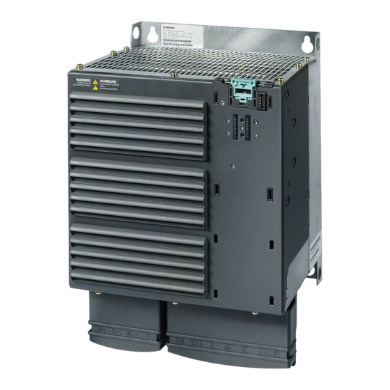
Power module
Hide thumbs
Also See for PM250:
- Hardware installation instructions (2 pages) ,
- Hardware installation manual (96 pages) ,
- Hardware installation manual (94 pages)

Related Manuals for Siemens PM250


Summary of Contents for Siemens PM250
- Page 1 SINAMICS G120 PM250 Power Module Hardware Installation Manual· 09/2012 SINAMICS Answers for industry. Siemens Parts...
- Page 3 ___________________ PM250 Power Module Introduction ___________________ Safety instructions ___________________ Installing/Mounting SINAMICS ___________________ Connecting SINAMICS G120 ___________________ PM250 Power Module Service and maintenance ___________________ Technical specifications Hardware Installation Manual ___________________ Accessories ___________________ Appendix Edition 09/2012 Siemens Parts 09/2012 A5E01003502B AD...
- Page 4 Note the following: WARNING Siemens products may only be used for the applications described in the catalog and in the relevant technical documentation. If products and components from other manufacturers are used, these must be recommended or approved by Siemens. Proper transport, storage, installation, assembly, commissioning, operation and maintenance are required to ensure that the products operate safely and without any problems.
-
Page 5: Table Of Contents
Table of contents Introduction..............................7 Power Modules PM250........................8 Block diagram ..........................9 Documents for the Inverter ......................10 Safety instructions ........................... 11 Residual risks..........................16 Installing/Mounting........................... 19 Installation conditions........................19 Air cooling requirements ......................20 Dimensions and drill pattern ......................22 Control Unit installation ........................29 Connecting .............................. 31 Safety notes for the electrical installation ..................31... - Page 6 Table of contents PM250 Power Module Hardware Installation Manual, 09/2012, A5E01003502B AD...
-
Page 7: Introduction
● PM240 Power Module with resistor braking and dc braking functions, supply voltage 3 AC 400 V ● PM250 Power Module with regenerative braking function, supply voltage 3 AC 400 V ● PM260 Power Module with regenerative braking function, supply voltage 3 AC 690 V Control Units and Power Modules are allowed to be combined in any possible configuration. -
Page 8: Power Modules Pm250
Introduction 1.1 Power Modules PM250 Power Modules PM250 Available Power Modules There are the following types of Power Modules with regenerative braking capacity. The given power rating values are defined for "high overload" operation. ● Unfiltered Power Modules 380V … 480 V, IP20, frame sizes D … F, 15 kW … 75 kW ●... -
Page 9: Block Diagram
Introduction 1.2 Block diagram Block diagram Block diagram Figure 1-1 Power Module PM250 PM250 Power Module Siemens Parts Hardware Installation Manual, 09/2012, A5E01003502B AD... -
Page 10: Documents For The Inverter
● SINAMICS G120D http://www.siemens.com/sinamics-g120d ● SIMATIC ET 200S FC http://www.siemens.com/et200s-fc ● SIMATIC ET 200pro FC http://www.siemens.com/et200pro-fc Application examples You find various application examples to the inverters under the following link: ● http://support.automation.siemens.com/WW/view/en/20208582/136000 PM250 Power Module Hardware Installation Manual, 09/2012, A5E01003502B AD... -
Page 11: Safety Instructions
It has to be ensured by the machine manufacturer, that the voltage drop between the beginning of the load system and the power drive system during operation with rated values does not exceed 4 %. PM250 Power Module Siemens Parts Hardware Installation Manual, 09/2012... - Page 12 Take particular notice of the general and regional installation and safety regulations regarding work on dangerous voltage installations (e.g. EN 50178) as well as the relevant regulations regarding the correct use of tools and personal protective equipment (PPE). PM250 Power Module Hardware Installation Manual, 09/2012, A5E01003502B AD...
- Page 13 Only suitably qualified personnel trained in the setup, installation, commissioning and operation of the product should carry out work on the equipment. PM250 Power Module Siemens Parts Hardware Installation Manual, 09/2012, A5E01003502B AD...
- Page 14 Ensure that the inverter is configured for the correct supply voltage – it must not be connected to a higher voltage supply. PM250 Power Module Hardware Installation Manual, 09/2012, A5E01003502B AD...
- Page 15 Either protective ground conductor cross-sections ≥ 10 mm (8 AWG) Cu or installation of a second protective ground conductor with both having the same cross-section as the line input cable. PM250 Power Module Siemens Parts Hardware Installation Manual, 09/2012, A5E01003502B AD...
-
Page 16: Residual Risks
2.1 Residual risks Repair WARNING Repairs on equipment may only be carried out by Siemens Service, by repair centers authorized by Siemens or by authorized personnel who are thoroughly acquainted with all the warnings and operating procedures contained in this manual. - Page 17 For more information about residual risks of the components in a power drive system, see the relevant chapters in the technical user documentation. PM250 Power Module Siemens Parts Hardware Installation Manual, 09/2012, A5E01003502B AD...
- Page 18 Safety instructions 2.1 Residual risks PM250 Power Module Hardware Installation Manual, 09/2012, A5E01003502B AD...
-
Page 19: Installing/Mounting
● Ensure that earthing and grounding practices for each Power Module and the cabinet follows the guidelines given in this document. CAUTION The Power Module MUST NOT be mounted horizontally. PM250 Power Module Siemens Parts Hardware Installation Manual, 09/2012, A5E01003502B AD... -
Page 20: Air Cooling Requirements
6. Avoid cooling air short circuit using air barriers, if necessary Figure 3-1 Air barriers for avoiding cooling air short circuits 7. Provide an adequate cubicle with sufficient air vent and suitable air strainer PM250 Power Module Hardware Installation Manual, 09/2012, A5E01003502B AD... - Page 21 The power losses of Power Module, output reactor and sine-wave filter are valid for the following operating conditions: ● Rated output current ● 50 Hz output frequency ● 4 kHz pulse frequency) Further information is given in the technical data. PM250 Power Module Siemens Parts Hardware Installation Manual, 09/2012, A5E01003502B AD...
-
Page 22: Dimensions And Drill Pattern
40 mm Additional distance to the front with Control Unit CU240E 1.57 inches 65 mm Additional distance to the front with Control Units CU240S … and 2.56 inches CU230P-2 … PM250 Power Module Hardware Installation Manual, 09/2012, A5E01003502B AD... - Page 23 40 mm Additional distance to the front with Control Unit CU240E 1.57 inches 65 mm Additional distance to the front with Control Units CU240S … and 2.56 inches CU230P-2 … PM250 Power Module Siemens Parts Hardware Installation Manual, 09/2012, A5E01003502B AD...
- Page 24 40 mm Additional distance to the front with Control Unit CU240E 1.57 inches 65 mm Additional distance to the front with Control Units CU240S … and 2.56 inches CU230P-2 … PM250 Power Module Hardware Installation Manual, 09/2012, A5E01003502B AD...
- Page 25 40 mm Additional distance to the front with Control Unit CU240E 1.57 inches 65 mm Additional distance to the front with Control Unit CU240S … and 2.56 inches CU230P-2 … PM250 Power Module Siemens Parts Hardware Installation Manual, 09/2012, A5E01003502B AD...
- Page 26 40 mm Additional distance to the front with Control Unit CU240E 1.57 inches 65 mm Additional distance to the front with Control Unit CU240S … and 2.56 inches CU230P-2 … PM250 Power Module Hardware Installation Manual, 09/2012, A5E01003502B AD...
- Page 27 40 mm Additional distance to the front with control unit CU240E 1.57 inches 65 mm Additional distance to the front with control unit CU240S … and 2.56 inches CU230P-2 … PM250 Power Module Siemens Parts Hardware Installation Manual, 09/2012, A5E01003502B AD...
- Page 28 40 mm Additional distance to the front with control unit CU240E 1.57 inches 65 mm Additional distance to the front with control unit CU240S … and 2.56 inches CU230P-2 … PM250 Power Module Hardware Installation Manual, 09/2012, A5E01003502B AD...
-
Page 29: Control Unit Installation
The process of fitting the Control Unit to the Power Module is the same technique independent from the type of Control Unit or Power Module. Figure 3-9 Fitting the Control Unit CU240S to the Power Module FSC PM250 Power Module Siemens Parts Hardware Installation Manual, 09/2012, A5E01003502B AD... - Page 30 Installing/Mounting 3.4 Control Unit installation PM250 Power Module Hardware Installation Manual, 09/2012, A5E01003502B AD...
-
Page 31: Connecting
Ensure that the inverter is configured for the correct supply voltage – it must not be connected to a higher voltage supply. WARNING Filtered drives can only be used on power systems with grounded starpoint. PM250 Power Module Siemens Parts Hardware Installation Manual, 09/2012, A5E01003502B AD... -
Page 32: Power Distribution Systems
Filtered drives can only be used on power systems with grounded starpoint. Note For fulfilling the protection class I according to EN 61140 the input and output supply voltages have to be earthed. PM250 Power Module Hardware Installation Manual, 09/2012, A5E01003502B AD... -
Page 33: Operation With Ungrounded (It) Supplies
● The output cables are less than 50 m (164 ft) screened or 100 m (328 ft) unscreened. If no RCD is used, the touch protection can be achieved by double insulation or by separating the Power Module from the mains system using a transformer. PM250 Power Module Siemens Parts Hardware Installation Manual, 09/2012, A5E01003502B AD... -
Page 34: Motor Cable Length And Cross Section
Ensure that the appropriate circuit-breakers or fuses with the specified current rating are connected between the power supply and the inverter. The technical data contain information about the circuit breaker and fuses Auto-Hotspot. PM250 Power Module Hardware Installation Manual, 09/2012, A5E01003502B AD... - Page 35 For power cables larger than 10 mm² (Cu) or 16 mm² (Al) the earth cable must be at least 10 mm² (Cu) or 16 mm² (Al), but need not exceed these sizes. PM250 Power Module Siemens Parts Hardware Installation Manual, 09/2012, A5E01003502B AD...
-
Page 36: Access To Power And Motor Terminals
The cover can then be pushed upwards and locked into position, as shown in the figure below. Figure 4-2 Access to power and motor terminals on FSD, FSE and FSF PM250 Power Module Hardware Installation Manual, 09/2012, A5E01003502B AD... -
Page 37: Power And Motor Connections
The figures below show the layout of the power and motor terminals of the Power Module. Figure 4-3 Power and motor terminals FSC Figure 4-4 Power and motor terminals FSD … FSF PM250 Power Module Siemens Parts Hardware Installation Manual, 09/2012, A5E01003502B AD... - Page 38 IP00 protection level. The figure shows a Power Module FSF with two 50 mm² cables on each terminal, which makes it impossible to close the terminals cover. PM250 Power Module Hardware Installation Manual, 09/2012, A5E01003502B AD...
-
Page 39: Esd Guidelines
For all frame sizes the Screen Termination Kit is supplied as an optional extra. It allows easy and efficient connection of the necessary screening. For further details on the Screen Termination Kit, please refer to the SINAMICS G120 catalog. PM250 Power Module Siemens Parts Hardware Installation Manual, 09/2012, A5E01003502B AD... - Page 40 Use suitable clips to fix motor and power cable screen securely to metal back plate ⑤ Screen cables ⑥ Screen Termination Kit ⑦ Gromments Figure 4-5 Example of wiring to minimize the effect of EMI PM250 Power Module Hardware Installation Manual, 09/2012, A5E01003502B AD...
-
Page 41: Service And Maintenance
The actual intervals at which maintenance procedures are to be performed depend on the installation conditions and the operating conditions. Siemens offers its customers support in the form of a service contract. For further details, contact your regional office or sales office. -
Page 42: Replacing The Cooling Fan
3. Slide the cooling fan out from the inverter Figure 5-1 Cooling fan removal FSC (5.5 kW … 15 kW) Installation For re-installation, carry out the above steps in reverse order. PM250 Power Module Hardware Installation Manual, 09/2012, A5E01003502B AD... - Page 43 Cooling fan removal FSD and FSE (15 kW … 37 kW) Figure 5-3 Cooling fan removal FSF (45 kW … 75 kW) Installation For re-installation, carry out the above steps in reverse order. PM250 Power Module Siemens Parts Hardware Installation Manual, 09/2012, A5E01003502B AD...
- Page 44 Service and maintenance 5.2 Replacing the cooling fan PM250 Power Module Hardware Installation Manual, 09/2012, A5E01003502B AD...
-
Page 45: Technical Specifications
Anti-condensation heaters are commonly used to prevent the formation of condensation. Pollution According pollution degree level 2 Do not install the SINAMICS G120 in an environment which contains atmospheric pollutants such as dust and/or corrosive gases. PM250 Power Module Siemens Parts Hardware Installation Manual, 09/2012, A5E01003502B AD... - Page 46 15.2 45.0 38.3 31.5 27.0 22.5 20.3 18.0 60.0 51.0 42.0 36.0 30.0 27.0 24.0 75.0 63.8 52.5 45.0 37.5 33.8 30.0 90.0 76.5 63.0 54.0 45.0 40.5 36.0 93.5 77.0 PM250 Power Module Hardware Installation Manual, 09/2012, A5E01003502B AD...
- Page 47 6600 9800 13000 3300 6600 9800 13000 Installation altitude above sea level [m] Installation altitude above sea level [m] [ft] [ft] Current derating for altitude Voltage derating for altitude PM250 Power Module Siemens Parts Hardware Installation Manual, 09/2012, A5E01003502B AD...
- Page 48 Output base load current (LO) Fuse Required cooling air flow Input Cable / 4.0 … 10 4.0 … 10 4.0 … 10 Output Cable 12 … 8 12 … 8 12 … 8 Weight PM250 Power Module Hardware Installation Manual, 09/2012, A5E01003502B AD...
- Page 49 Required cooling air flow Input Cable / 25.0 … 35.0 25.0 … 35.0 Output Cable 3 … 2 3 … 2 Weight filtered 21.0 21.0 46.3 46.3 unfiltered 16.0 16.0 35.3 35.3 PM250 Power Module Siemens Parts Hardware Installation Manual, 09/2012, A5E01003502B AD...
- Page 50 35.0 … 120 35.0 … 120 35.0 … 120 Output Cable 2 … 4/0 2 … 4/0 2 … 4/0 Weight filtered 51.0 51.0 51.0 unfiltered 36.0 36.0 36.0 79.4 79.4 79.4 PM250 Power Module Hardware Installation Manual, 09/2012, A5E01003502B AD...
-
Page 51: Accessories
Sine-wave filter The sine-wave filter is designed to limit the rate of rise of voltage and the capacitive charge or discharge currents which usually occur with inverter operation. PM250 Power Module Siemens Parts Hardware Installation Manual, 09/2012, A5E01003502B AD... - Page 52 Line fuses and contactor have to be installed between the line filter and the mains system. L1’ L3’ L1’ L3’ Connecting power components with sine- Connecting power components with output wave filter reactor PM250 Power Module Hardware Installation Manual, 09/2012, A5E01003502B AD...
- Page 53 Power Module above it in a space-saving construction. Up to two base components can be mounted above one another. Figure 7-1 Mounting base components PM250 Power Module Siemens Parts Hardware Installation Manual, 09/2012, A5E01003502B AD...
-
Page 54: Line Filter
Figure 7-2 Connecting the line filter as base component The overall and mounting dimensions of the line filter are written in the technical specifications. PM250 Power Module Hardware Installation Manual, 09/2012, A5E01003502B AD... - Page 55 The admissible ambient conditions of the line filter are the same as for the suitable Power Module. This applies to: ● storage and transport temperature ● operating temperature ● relative humidity ● shock and vibration load PM250 Power Module Siemens Parts Hardware Installation Manual, 09/2012, A5E01003502B AD...
- Page 56 Overall dimensions Width 190 mm Height 362 mm Depth 55 mm Fixing dimensions Width 156 mm Height 232 mm Fixing screw 4 × M5 Weight 2.3 kg Possible as base component PM250 Power Module Hardware Installation Manual, 09/2012, A5E01003502B AD...
-
Page 57: Output Reactor
Figure 7-4 Connecting the output reactor as base component The overall and mounting dimensions of the output reactor are written in the technical specifications. PM250 Power Module Siemens Parts Hardware Installation Manual, 09/2012, A5E01003502B AD... - Page 58 Figure 7-5 Connecting the output reactor as lateral component For more information see http://support.automation.siemens.com/WW/view/en/22103628 Technical specifications of the output reactors The major electrical specification of the output reactors is the same as for the suitable Power Module. This applies to: ●...
- Page 59 Height 232 mm 176 mm 176 mm Fixing screw 4 × M5 4 × M6 4 × M6 Weight 9 kg 10.5 kg 16 kg Possible as base component PM250 Power Module Siemens Parts Hardware Installation Manual, 09/2012, A5E01003502B AD...
- Page 60 101 mm Height 176 mm 176 mm 200 mm Fixing screw 4 × M6 4 × M6 4 × M8 Weight 10.5 kg 10.5 kg 25 kg Possible as base component PM250 Power Module Hardware Installation Manual, 09/2012, A5E01003502B AD...
- Page 61 Height 264 mm 200 mm 264 mm Fixing screw 4 × M8 4 × M8 4 × M8 Weight 52 kg 52 kg 52 kg Possible as base component PM250 Power Module Siemens Parts Hardware Installation Manual, 09/2012, A5E01003502B AD...
-
Page 62: Sine-Wave Filter
The sine-wave filter is connected to the motor through terminals. Figure 7-6 Connecting the sine-wave filter as base component The overall and mounting dimensions of the sine-wave filter are written in the technical specifications. PM250 Power Module Hardware Installation Manual, 09/2012, A5E01003502B AD... - Page 63 The sine-wave filter for Power Modules with a rated power (HO) of more than 11 kW has to be mounted laterally. Figure 7-7 Connecting the sine-wave filter as lateral component For more information see http://support.automation.siemens.com/WW/view/en/29522775 PM250 Power Module Siemens Parts Hardware Installation Manual, 09/2012, A5E01003502B AD...
- Page 64 100 mm Fixing dimensions Width 167 mm 167 mm Height 323 mm 323 mm Fixing screw 4 × M5 4 × M5 Weight 12.0 kg 23.0 kg Possible as base component PM250 Power Module Hardware Installation Manual, 09/2012, A5E01003502B AD...
- Page 65 Depth 127 mm 127 mm 132 mm Fixing screw 4 × M6 4 × M6 4 × M8 Weight 24 kg 34 kg 45 kg Possible as base component PM250 Power Module Siemens Parts Hardware Installation Manual, 09/2012, A5E01003502B AD...
- Page 66 100 mm Fixing dimensions Width 320 mm 320 mm Depth 255 mm 155 mm Fixing screw 4 × M8 4 × M8 Weight 63 kg 80 kg Possible as base component PM250 Power Module Hardware Installation Manual, 09/2012, A5E01003502B AD...
-
Page 67: Brake Relay
The Brake Relay can be panel mounted, wall mounted or mounted on the shield connection kit. For more information see http://support.automation.siemens.com/WW/view/de/23623179 Connecting the Brake Relay to the Power Module Connect one end of the cable form to the Brake Relay. - Page 68 The Brake Relay has to be connected to protective earth, if the motor brake is supplied by a PELV circuit. Connecting the Safe Brake Relay to the motor brake The Safe Brake Relay can only control motor brakes with 24V power supply. Figure 7-9 Safe Brake Relay connection PM250 Power Module Hardware Installation Manual, 09/2012, A5E01003502B AD...
- Page 69 1 DC 30 V DC, 12 A Output voltage 24 V Output current max. 2 A 1) External controlled power supply is necessary. Recommended voltage: DC 26 V PM250 Power Module Siemens Parts Hardware Installation Manual, 09/2012, A5E01003502B AD...
-
Page 70: Screen Termination Kit
The screen termination kits provides for the termination of at least 4 screened cables. Mounting the screen termination kit The mounting description of the screen termination kit is available in the internet: http://support.automation.siemens.com/WW/view/de/23621093 PM250 Power Module Hardware Installation Manual, 09/2012, A5E01003502B AD... -
Page 71: Appendix
European government organization. This approach allows the use of standards that are still in preparation. EMC Standards The SINAMICS G120 drives have been tested in accordance with the EMC Product Standard EN 61800-3:2004. PM250 Power Module Siemens Parts Hardware Installation Manual, 09/2012, A5E01003502B AD... -
Page 72: Definition Of The Emc Environment And Categories
Note A professional is a person or an organization having necessary skills in installing and/or commissioning a Power Drive System (PDS), including their EMC aspects. PM250 Power Module Hardware Installation Manual, 09/2012, A5E01003502B AD... - Page 73 Note All drives should be installed and commissioned in accordance with the manufacturer’s guidelines and in accordance with good EMC practices. For further information refer to SIEMENS application note "EMC Design Guidelines". PM250 Power Module Siemens Parts Hardware Installation Manual, 09/2012, A5E01003502B AD...
-
Page 74: Standards
The SINAMICS G120 Power Modules PM240 fulfill the requirements of the SEMI F47-0706 standard. ISO 9001 Siemens plc operates a quality management system, which complies with the requirements of ISO 9001. Certificates can be downloaded from the internet under the following link: http://support.automation.siemens.com/WW/view/en/22339653/134200... -
Page 75: Abbreviations
PELV Protection by extra low voltage Power Module Personal protective equipment RCCB Residual current circuit breaker Residual current device Radio frequency interference SELV Safety extra low voltage Variable torque PM250 Power Module Siemens Parts Hardware Installation Manual, 09/2012, A5E01003502B AD... - Page 76 Appendix A.4 Abbreviations PM250 Power Module Hardware Installation Manual, 09/2012, A5E01003502B AD...
-
Page 77: Index
European Machinery Directive, 74 Operation with Residual Current Devices (RCD), 33 Operation with ungrounded supplies, 33 First Environment, 72 Output reactor Fitting the Control Unit to the Power Module, 29 Installing, 57 PM250 Power Module Siemens Parts Hardware Installation Manual, 09/2012, A5E01003502B AD... - Page 78 Self certification, 71 Service life of the fan, 42 SINAMICS G120 range, 7 Sine-wave filter Installing, 62 Standards, 74 EC/89/336, 71 EN 60950, 32 EN 61140, 32 EN 61800-3, 71, 72 PM250 Power Module Hardware Installation Manual, 09/2012, A5E01003502B AD...
- Page 79 Siemens Parts...
- Page 80 Siemens AG We reserve the right to make technical changes. Industry Sector © Siemens AG 2012 Drive Technologies Motion Control Systems Postfach 3180 91050 ERLANGEN GERMANY www.siemens.com/sinamics-g120...
Need help?
Do you have a question about the PM250 and is the answer not in the manual?
Questions and answers