Siemens SINAMICS G120 Hardware Installation Manual
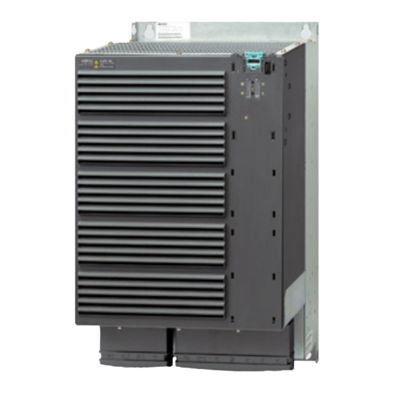
Power module
Hide thumbs
Also See for SINAMICS G120:
- List manual (1256 pages) ,
- Manual (732 pages) ,
- Operating instructions manual (550 pages)

Related Manuals for Siemens SINAMICS G120


Summary of Contents for Siemens SINAMICS G120
- Page 1 Hardware Installation Manual SINAMICS SINAMICS G120 Converters PM250 Power Module Edition 04/2021 www.siemens.com/drives...
- Page 3 Changes in this manual Fundamental safety instructions Introduction A5E36265179B-AB Installing/mounting SINAMICS G120 PM250 Power Module Connection Operation, repair, and maintenance Hardware Installation Manual Technical specifications Spare parts and accessories Appendix Edition 04/2021 04/2021 A5E36265179B-AB...
- Page 4 Note the following: WARNING Siemens products may only be used for the applications described in the catalog and in the relevant technical documentation. If products and components from other manufacturers are used, these must be recommended or approved by Siemens. Proper transport, storage, installation, assembly, commissioning, operation and maintenance are required to ensure that the products operate safely and without any problems.
-
Page 5: Table Of Contents
Table of contents Changes in this manual ........................5 Fundamental safety instructions......................7 General safety instructions....................7 Equipment damage due to electric fields or electrostatic discharge ........13 Warranty and liability for application examples ..............14 Security information ......................15 Residual risks of power drive systems ................. - Page 6 Table of contents Technical specifications ........................53 Overload capability of the converter ................... 54 Ambient conditions......................56 General technical data, PM250................... 57 Power-dependent data....................... 58 Current derating depending on the pulse frequency ............60 Restrictions for special ambient conditions ................. 61 Electromagnetic compatibility of the inverter ..............
-
Page 7: Changes In This Manual
Changes in this manual Changes with respect to the manual, edition 01/2016 • Dimension drawing for Power Modules FSD, FSE, FSF corrected. Mounting the Power Modules (Page 26) • Degree of protection for output reactors corrected. Assignment of converter FSD (18.5 kW and 22 kW) and output reactors corrected. Output reactor (Page 72) •... - Page 8 Changes in this manual PM250 Power Module Hardware Installation Manual, 04/2021, A5E36265179B-AB...
-
Page 9: Fundamental Safety Instructions
Fundamental safety instructions General safety instructions WARNING Electric shock and danger to life due to other energy sources Touching live components can result in death or severe injury. • Only work on electrical devices when you are qualified for this job. •... - Page 10 Fundamental safety instructions 2.1 General safety instructions WARNING Risk of electric shock and fire from supply networks with an excessively low impedance Excessively high short-circuit currents can lead to the protective devices not being able to interrupt these short-circuit currents and being destroyed, and thus causing electric shock or a fire.
- Page 11 Fundamental safety instructions 2.1 General safety instructions WARNING Electric shock due to unconnected cable shield Hazardous touch voltages can occur through capacitive cross-coupling due to unconnected cable shields. • As a minimum, connect cable shields and the conductors of power cables that are not used (e.g.
- Page 12 • Therefore, if you move closer than 20 cm to the components, be sure to switch off radio devices or mobile telephones. • Use the "SIEMENS Industry Online Support app" only on equipment that has already been switched off. NOTICE...
- Page 13 Fundamental safety instructions 2.1 General safety instructions WARNING Fire due to inadequate ventilation clearances Inadequate ventilation clearances can cause overheating of components with subsequent fire and smoke. This can cause severe injury or even death. This can also result in increased downtime and reduced service lives for devices/systems.
- Page 14 Fundamental safety instructions 2.1 General safety instructions WARNING Unexpected movement of machines caused by inactive safety functions Inactive or non-adapted safety functions can trigger unexpected machine movements that may result in serious injury or death. • Observe the information in the appropriate product documentation before commissioning. •...
-
Page 15: Equipment Damage Due To Electric Fields Or Electrostatic Discharge
Fundamental safety instructions 2.2 Equipment damage due to electric fields or electrostatic discharge Equipment damage due to electric fields or electrostatic discharge Electrostatic sensitive devices (ESD) are individual components, integrated circuits, modules or devices that may be damaged by either electric fields or electrostatic discharge. NOTICE Equipment damage due to electric fields or electrostatic discharge Electric fields or electrostatic discharge can cause malfunctions through damaged individual... -
Page 16: Warranty And Liability For Application Examples
Fundamental safety instructions 2.3 Warranty and liability for application examples Warranty and liability for application examples Application examples are not binding and do not claim to be complete regarding configuration, equipment or any eventuality which may arise. Application examples do not represent specific customer solutions, but are only intended to provide support for typical tasks. -
Page 17: Security Information
Siemens’ products and solutions undergo continuous development to make them more secure. Siemens strongly recommends that product updates are applied as soon as they are available and that the latest product versions are used. Use of product versions that are no longer supported, and failure to apply the latest updates may increase customer’s exposure to cyber... -
Page 18: Residual Risks Of Power Drive Systems
Fundamental safety instructions 2.5 Residual risks of power drive systems Residual risks of power drive systems When assessing the machine- or system-related risk in accordance with the respective local regulations (e.g., EC Machinery Directive), the machine manufacturer or system installer must take into account the following residual risks emanating from the control and drive components of a drive system: 1. -
Page 19: Introduction
Introduction Description The Power Module is part of the modular SINAMICS G120 converter family. A converter consists of a Control Unit and a Power Module. You can operate the Power Module with one of the following Control Units. • CU230P-2 •... - Page 20 Introduction Permissible motors Note Motors for converter operation Only use motors that are suitable for operation with converters with a DC link. For the Power Modules, induction motors are permissible in the range from 25% … 150% of the converter power without any restrictions. PM250 Power Module Hardware Installation Manual, 04/2021, A5E36265179B-AB...
-
Page 21: Installing/Mounting
Installing/mounting EMC-compliant installation of a machine or system The converter is designed for operation in industrial environments where strong electromagnetic fields are to be expected. Reliable and disturbance-free operation is only ensured for EMC-compliant installation. To achieve this, subdivide the control cabinet and the machine or system into EMC zones: EMC zones Figure 4-1 Example of the EMC zones of a plant or machine... -
Page 22: Control Cabinet
Installing/mounting 4.1 EMC-compliant installation of a machine or system 4.1.1 Control cabinet • Assign the various devices to zones in the control cabinet. • Electromagnetically uncouple the zones from each other by means of one of the following actions: – Side clearance ≥ 25 cm –... -
Page 23: Cables
Installing/mounting 4.1 EMC-compliant installation of a machine or system 4.1.2 Cables Cables with a high level of interference and cables with a low level of interference are connected to the converter: • Cables with a high level of interference: – Cable between the line filter and converter –... - Page 24 Installing/mounting 4.1 EMC-compliant installation of a machine or system Figure 4-2 Routing converter cables inside and outside a control cabinet Routing cables outside the control cabinet • Maintain a minimum clearance of 25 cm between cables with a high level of interference and cables with a low level of interference.
- Page 25 Installing/mounting 4.1 EMC-compliant installation of a machine or system Requirements relating to shielded cables • Use cables with finely-stranded, braided shields. • Connect the shield to at least one end of the cable. Figure 4-3 Examples for EMC-compliant shield support •...
-
Page 26: Electromechanical Components
Grounding and high-frequency equipotential bonding measures in the control cabinet and in the plant/system Further information Additional information about EMC-compliant installation is available in the Internet: EMC installation guideline (https://support.industry.siemens.com/cs/ww/de/view/ 60612658/en) 4.1.3 Electromechanical components Surge voltage protection circuit • Connect surge voltage protection circuits to the following components: –... -
Page 27: Power Losses And Air Cooling Requirements
Installing/mounting 4.2 Power losses and air cooling requirements Power losses and air cooling requirements Cooling requirements To protect the components from overheating, the control cabinet requires a cooling air flow, which depends on the power loss of the individual components. Formula for calculating the cooling airflow: airflow [l/s] = power loss [W] * 0.86 / ΔT [K] •... -
Page 28: Mounting The Power Modules
Installing/mounting 4.3 Mounting the Power Modules Mounting the Power Modules Installing Rules for admissible mounting: • Only mount the Power Module in a vertical position with the motor connectors at the bottom. • Maintain the minimum clearances to other components. •... - Page 29 Installing/mounting 4.3 Mounting the Power Modules Frame size FSC Table 4-1 Dimensions depend on the Control Unit (CU) and Operator Panel (OP) Frame Overall depth in the cabinet [mm] size OP inserted? CU230P-2 CU240B/E-2 CU250S-2 Without OP With OP With blanking cover or with BOP-2 or IOP-2 Operator Panel Table 4-2 Cooling air clearances and fixing Frame...
- Page 30 Installing/mounting 4.3 Mounting the Power Modules Frame sizes FSD … FSF Table 4-3 Dimensions depend on the Control Unit (CU) and Operator Panel (OP) Frame Width Height [mm] Overall depth in the cabinet [mm] size [mm] without with OP inserted? CU230P-2 CU240B/E-2 CU250S-2...
- Page 31 Installing/mounting 4.3 Mounting the Power Modules Table 4-4 Drilling dimensions, cooling clearances and fixing Frame size Drilling dimensions Cooling air clearances Fixing/torque [mm] [mm] [Nm] Bottom Front FSD without filter 4 x M6 / 6 FSD with filter 4 x M6 / 6 FSE without filter 4 x M6 / 6 FSE with filter...
-
Page 32: Additional Components
Installing/mounting 4.4 Additional components Additional components Depending on the particular application, additional components may be required for your system. Information about additional components is provided in the following Sections: Connection overview (Page 39) Optional accessories (Page 69) PM250 Power Module Hardware Installation Manual, 04/2021, A5E36265179B-AB... -
Page 33: Connection
To protect against indirectly touching part of the motor circuit of a converter and to automatically shut down in the case of a fault according to DIN EN 60364-4-41 (VDE 0100-410). (http://support.automation.siemens.com/WW/view/en/103474630) WARNING Fire or electric shock due to unsuitable residual-current protective devices The converter may create a current through the protective conductor. - Page 34 The equipment must satisfy the following properties and general conditions: – super-resistant RCD/RCM type B, with a trip current of 300 mA. e.g. a SIQUENCE circuit breaker from Siemens. – Only one inverter is supplied from each RCD/RCM – The motor cables are shielded and are not longer than 50 m. You can find additional...
-
Page 35: Permissible Networks
Connection 5.1 Permissible networks Permissible networks Note Line requirement The machine manufacturer must ensure that in operation the voltage drop between the transformer input terminals and the inverter when operated with its rated values is less than 1%. The inverter is designed for the following power distribution systems according to IEC 60364-1 (2005). -
Page 36: Tn Line System
Connection 5.1 Permissible networks 5.1.1 TN line system A TN system transfers the PE protective con‐ ductor to the installed plant or system using a cable. Generally, in a TN system the neutral point is grounded. There are versions of a TN system with a grounded line conductor, e.g. -
Page 37: Tt Line System
Connection 5.1 Permissible networks 5.1.2 TT line system In a TT line system, the transformer ground‐ ing and the installation grounding are inde‐ pendent of one another. There are TT line supplies where the neutral conductor N is either transferred – or not. Note Operation in IEC or UL systems For installations in compliance with IEC, operation on TT line systems is permissible. -
Page 38: System
Connection 5.1 Permissible networks 5.1.3 IT system In an IT line system, all of the conductors are insulated with respect to the PE protective conductor – or connected to the PE protective conductor through an impedance. There are IT systems with and without transfer of the neutral conductor N. -
Page 39: Requirements For The Protective Conductor
Connection 5.2 Requirements for the protective conductor Requirements for the protective conductor Overview A high leakage current flows through the protective conductor in converter operation. The protective conductor of the converter must not be interrupted for safe touch protection in converter operation. - Page 40 Connection 5.2 Requirements for the protective conductor ① ④ The minimum cross-section of the protective conductor … depends on the cross-section of the line or motor feeder cable: • Line or motor feeder cable ≤ 16 mm ⇒ Minimum cross-section of the protective conductor = cross-section of the line or motor feeder cable •...
-
Page 41: Connection Overview
• For configurations in conformance with UL/cUL, use the UL/cUL-approved fuses, Class J or Siemens 3NE1 semiconductor fuses, which are specified in this manual. If you use semiconductor fuses as branch protection, then you must install them in the same electrical cabinet as the converter. - Page 42 5.3 Connection overview • Terminal voltage, V = 2000 V • Suitable for SPD applications, type 1 or type 2 Alternatively, use a surge protection device, article number 5SD7 424-1 from Siemens AG. PM250 Power Module Hardware Installation Manual, 04/2021, A5E36265179B-AB...
-
Page 43: Inverter Terminals
Connection 5.4 Inverter terminals Inverter terminals Table 5-1 Connection, cross-section and tightening torque for PM250 Power Modules Converter Line supply and motor connection Cross-section and tightening torque Stripped insula‐ Metric Imperial tion length Screw-type terminal 4 …10 mm , 2.3 Nm 12 …... -
Page 44: Connecting The Line Supply And Motor
Connection 5.5 Connecting the line supply and motor Connecting the line supply and motor Establishing the line and motor connection, frame size FSA The terminals are directly accessible. The terminals are directly accessible. Connect the phases of the line cable to terminals L1, L2, L3 and the protective conductor to PE. Connect the motor cable phases to terminals U2, V2, W2 and the protective conductor to Connections for frame sizes FSD …... - Page 45 Connection 5.5 Connecting the line supply and motor Connect cables at the converter so that they are EMC compliant Attach the cable tie holders to the Power Mod‐ ule as shown to the left in the diagram before you establish the connections. Fix the line connecting cable using a cable tie ①...
-
Page 46: Length Of Motor Cable
Connection 5.6 Length of motor cable Length of motor cable Always dimension the motor cable so that the ohmic losses are less than 5% of the converter power rating. The permissible length of the motor cable also depends on the quality of the motor cable and the converter pulse frequency. -
Page 47: Connecting The Motor To The Converter In A Star Or Delta Connection
Connection 5.7 Connecting the motor to the converter in a star or delta connection Connecting the motor to the converter in a star or delta connection Overview Standard induction motors up to a rated power of approximately 3 kW are usually connected in star/delta connection (Y/Δ) at 400 V/230 V. - Page 48 Connection 5.7 Connecting the motor to the converter in a star or delta connection PM250 Power Module Hardware Installation Manual, 04/2021, A5E36265179B-AB...
-
Page 49: Operation, Repair, And Maintenance
Operation, repair, and maintenance Operation Voltage dips and brief power interruptions For Power Modules, frame sizes FSD … FSF, voltage dips or power interruptions of up to 3 ms can cause the inverter to be shut down with fault F30003 or F30027. You can restart the inverter by acknowledging the fault using OFF1 and then entering a new ON command. -
Page 50: Repair
• Only commission the following persons to repair the converter: – Siemens customer service – A repair center that has been authorized by Siemens – Specialist personnel who are thoroughly acquainted with all the warnings and operating procedures contained in this manual. -
Page 51: Replacing Fans
Operation, repair, and maintenance 6.3 Replacing fans Replacing fans Service life of the fan The average service life of the fan is 40,000 hours. In practice, however, the service life may deviate from this value. Especially a dusty environment can block up the fan. The fan must be replaced in good time to ensure that the converter is ready for operation. - Page 52 Operation, repair, and maintenance 6.3 Replacing fans 1. Switch off the converter's supply voltage. 2. Wait for 5 minutes until the DC link capacitors have been discharged. 3. Disconnect all of the cables from the Power Module. ① ② 4. Release the fan cover ③...
- Page 53 Operation, repair, and maintenance 6.3 Replacing fans 1. Switch off the converter's supply voltage. 2. Wait for 5 minutes until the DC link capacitors have been discharged. 3. Disconnect all of the cables from the Power Module. ① ② 4. Release the four screws and remove the fan cover plate ③...
-
Page 54: Maintenance
Note The actual maintenance intervals depend on the installation and operating conditions. Siemens offers its customers support in the form of service contracts. For further information, contact your Siemens regional office or sales office via the link below: Siemens contact database (https://mall.industry.siemens.com/aspa_app?lang=en) . -
Page 55: Technical Specifications
Technical specifications Power loss of the Power Modules The power loss values specified are typical values. More information is provided on the Internet: Power loss data for partial load operation (https://support.industry.siemens.com/cs/ww/en/ view/94059311) PM250 Power Module Hardware Installation Manual, 04/2021, A5E36265179B-AB... -
Page 56: Overload Capability Of The Converter
Low Overload. We recommend using the "SIZER" engineering software to select the converter. You can find additional information about SIZER on the Internet: Download SIZER (http://support.automation.siemens.com/WW/view/en/ 10804987/130000) Load cycles and typical applications: "Low Overload" load cycle "High Overload" load cycle The "Low Overload"... - Page 57 Technical specifications 7.1 Overload capability of the converter Typical converter load cycles PM250 Power Module Hardware Installation Manual, 04/2021, A5E36265179B-AB...
-
Page 58: Ambient Conditions
Technical specifications 7.2 Ambient conditions Ambient conditions Ambient conditions during operation Property Version Ambient conditions for transport in the transport packaging Climatic ambient conditions ‑ 40° C … + 70° C, according to Class 2K4 to EN 60721‑3‑2 maximum humidity 95% at 40 °C Mechanical ambient condi‐... -
Page 59: General Technical Data, Pm250
Technical specifications 7.3 General technical data, PM250 General technical data, PM250 Property Version Line voltage 380 … 480 V 3 AC ± 10% Line impedance Uk < 1% (RSC > 100), a line reactor is not permitted Output voltage 3-phase 0 VAC … input voltage x 0.87 (max.) Input frequency 50 Hz …... -
Page 60: Power-Dependent Data
Technical specifications 7.4 Power-dependent data Power-dependent data Note The values for Low Overload (LO) are identical with those of the rated values. Table 7-1 PM250, IP20, Frame Size C, 3-ph. AC 380 V … 480 V Article No. 6SL3225-0BE25-5AA1 6SL3225-0BE27-5AA1 6SL3225-0BE31-1AA1 LO base load output 7.5 kW... - Page 61 < 60 dB < 65 dB Weight 51 kg 51 kg 51 kg You can find information about other permissible overcurrent protection devices on the Internet Protective devices for PM250 Power Modules (https:// support.industry.siemens.com/cs/ww/en/view/109795389) PM250 Power Module Hardware Installation Manual, 04/2021, A5E36265179B-AB...
-
Page 62: Current Derating Depending On The Pulse Frequency
Technical specifications 7.5 Current derating depending on the pulse frequency Current derating depending on the pulse frequency Article No. LO base LO baseload output current [A] at a pulse frequency of… load 6SL3225-… 4 kHz 6 kHz 8 kHz 10 kHz 12 kHz 14 kHz 16 kHz... -
Page 63: Restrictions For Special Ambient Conditions
Technical specifications 7.6 Restrictions for special ambient conditions Restrictions for special ambient conditions Maximum current at low speeds NOTICE Overheating the converter due to unsuitable load Loading the converter with a high output current and at the same time with a low output frequency can cause the current-conducting components in the converter to overheat. - Page 64 Technical specifications 7.6 Restrictions for special ambient conditions Current de-rating depending on the ambient operating temperature The Control Unit and operator panel can restrict the maximum permissible operating ambient temperature of the Power Module. Current derating as a function of the installation altitude The permissible converter output current is reduced above an installation altitude of 1000 m.
-
Page 65: Electromagnetic Compatibility Of The Inverter
Technical specifications 7.7 Electromagnetic compatibility of the inverter Electromagnetic compatibility of the inverter EMC (electromagnetic compatibility) means that the devices function satisfactorily without interfering with other devices and without being disrupted by other devices. EMC applies when the emitted interference (emission level) and the interference immunity are matched with each other. -
Page 66: Assigning The Inverter To Emc Categories
The converters have been tested in accordance with the EMC product standard EN 61800-3. You can find the Declaration of Conformity on the Internet: Declaration of Conformity (http://support.automation.siemens.com/WW/view/en/ 58275445) Requirements for electromagnetic compatibility To comply with the requirements of EN 61800‑3, all drives must be installed in accordance with the manufacturer's instructions and EMC directives. - Page 67 Technical specifications 7.7 Electromagnetic compatibility of the inverter Compliance with EMC limits with unfiltered devices (https://support.industry.siemens.com/ cs/ww/en/view/109750634) Field-conducted, high-frequency noise emission of an unfiltered inverter When installed professionally in accordance with EMC guidelines, the inverters fulfill the requirements of the standard.
-
Page 68: Emc Limit Values In South Korea
You can find additional information about EMC-compliant configuration of the plant or system on the Internet: EMC installation guideline (http://support.automation.siemens.com/WW/view/en/ 60612658) The final statement on compliance with the applicable standard is given by the respective label attached to the individual device. -
Page 69: Spare Parts And Accessories
Spare parts and accessories Spare parts compatibility Continuous development within the scope of product maintenance Converter components are being continuously developed within the scope of product maintenance. Product maintenance includes, for example, measures to increase the ruggedness or hardware changes which become necessary as components are discontinued. These further developments are "spare parts-compatible"... -
Page 70: Spare Parts
Article No. cover kit Frame sizes FSD and FSE 6SL3200-0SM11-0AA0 Frame size FSF 6SL3200-0SM12-0AA0 More information You can find more information on orderable repair and wearing parts or consumables on the Internet: Spare parts (https://www.automation.siemens.com/sow?sap-language=EN) PM250 Power Module Hardware Installation Manual, 04/2021, A5E36265179B-AB... -
Page 71: Optional Accessories
Spare parts and accessories 8.3 Optional accessories Optional accessories Which components are available? • Line filter • Output reactors • Sine-wave filter • Brake Relay and Safe Brake Relay Reactors and filters are designed for Power Modules, frame size FSC as base components. Reactors and filters as base components (Page 69) 8.3.1 Reactors and filters as base components... - Page 72 Spare parts and accessories 8.3 Optional accessories External filters are available for Category C2 or C1 according to EN 61800-3. Details are provided in the following tables. NOTICE Overloading of the line filter due to use in unsuitable networks The line filter is only suitable for operation on TN or TT networks with a grounded neutral point. The line filter is damaged if operated on all other networks.
- Page 73 Spare parts and accessories 8.3 Optional accessories Figure 8-3 FSF dimensions Figure 8-4 Mounting position FSF Table 8-1 Dimensions and weights Article No. Overall dimensions Drilling dimensions Mounting Weigh (mm) (mm) t (kg) Screws/torque (Nm) 6SL3203-0BD23-8SA0 4 x M5 / 3.0 6SL3203-0BE32-5AA0 4 x M8 / 13 12.4...
-
Page 74: Output Reactor
Spare parts and accessories 8.3 Optional accessories Table 8-3 Assignment table Line filter Power Module Article No. Catego‐ Article No. Frame size 6SL3203-0BD23-8SA0 6SL3225-0BE25-5AA0 6SL3225-0BE27-5AA0 6SL3225-0BE31-1AA0 6SL3203-0BE32-5AA0 6SL3225-0BE34-5AA0 6SL3225-0BE35-5AA0 6SL3225-0BE37-5AA0 8.3.3 Output reactor Mounting position PM250 Power Module Hardware Installation Manual, 04/2021, A5E36265179B-AB... - Page 75 Spare parts and accessories 8.3 Optional accessories Clearances to other devices Keep shaded areas free of any devices and components. Figure 8-5 Minimum clearances of the output reactor to other devices, space-saving mounting examples If you use an output reactor, then it is not permissible that the output frequency exceeds 150 Hz. It is not permissible that the pulse frequency is higher than 4 kHz.
- Page 76 Spare parts and accessories 8.3 Optional accessories Dimensions and drilling patterns Figure 8-6 Output reactor as base component for frame size FSC Figure 8-7 Standalone output reactor for frame sizes FSD … FSF Table 8-4 Dimensions and weights Article number Overall dimensions Drilling dimensions Tightening...
- Page 77 Spare parts and accessories 8.3 Optional accessories Article number Overall dimensions Drilling dimensions Tightening Weig (mm) (mm) screws/torque (Nm) (kg) 6SE6400-3TC07-5ED0 91.5 4 x M8 / 13 26.5 6SE6400-3TC14-5FD0 4 x M8 / 13 6SE6400-3TC15-4FD0 4 x M8 / 13 6SE6400-3TC14-5FD0 4 x M8 / 13 Technical specifications and assignment tables...
-
Page 78: Sine-Wave Filter
Spare parts and accessories 8.3 Optional accessories 8.3.4 Sine-wave filter The sine-wave filter at the converter output limits the voltage rate of rise and the peak voltages at the motor winding. The maximum permissible length of motor feeder cables is increased to 300 m. - Page 79 Spare parts and accessories 8.3 Optional accessories Figure 8-10 Dimensions - standalone filter Figure 8-11 Mounting position - standalone filter Table 8-7 Dimensions and weights Sine-wave filter Overall dimensions Drilling dimensions Tightening Weigh (mm) (mm) screws/torque t (kg) (Nm) Footprint filter 6SL3202-0AE22-0SA0 4 x M5 / 3.0 6SL3202-0AE23-3SA0...
- Page 80 Spare parts and accessories 8.3 Optional accessories Technical specifications and assignment tables Table 8-8 Technical specifications Article No. Connection (mm De‐ dU/dt Maxi‐ Power gree limit loss [W] at Motor / PE Power Module of pro‐ [V/ms] voltage 50 Hz tec‐...
-
Page 81: Connecting A Motor Holding Brake
Spare parts and accessories 8.3 Optional accessories 8.3.5 Connecting a motor holding brake The converter uses the Brake Relay to control the motor holding brake. Two types of Brake Relay exist: • The Brake Relay controls the motor holding brake •... -
Page 82: Mounting And Connecting The Safe Brake Relay
Spare parts and accessories 8.3 Optional accessories 8.3.5.2 Mounting and connecting the Safe Brake Relay Safe Brake Relay 8.3.5.3 Technical data of the brake relay Brake Relay Safe Brake Relay 6SL3252-0BB00-0AA0 6SL3252-0BB01-0AA0 Input voltage via the Power Module 20.4 ... 28.8 VDC Input current via the Power Module Max. -
Page 83: Shield Connection Kit
Article numbers of the shield connection kit • FSC: 6SL3262-1AC00-0DA0 • FSD: 6SL3262-1AD00-0DA0 • FSE: 6SL3262-1AD00-0DA0 • FSF: 6SL3262-1AF00-0DA0 More information More information is provided on the Internet: Shield connection kit (https://support.industry.siemens.com/cs/ww/en/view/32052656) PM250 Power Module Hardware Installation Manual, 04/2021, A5E36265179B-AB... - Page 84 Spare parts and accessories 8.3 Optional accessories PM250 Power Module Hardware Installation Manual, 04/2021, A5E36265179B-AB...
-
Page 85: Appendix
9.1.1 Overview of the manuals Manuals with additional information that can be downloaded: EMC-compliant control cabinet installation • PM250 Hardware Installation Manual (https://support.industry.siemens.com/cs/ww/de/ view/64875934/en) Installing Power Modules, reactors and filters. Technical specifications, maintenance (this manual) • CU230P-2 operating instructions (https://support.industry.siemens.com/cs/ww/en/ view/109782866) Installing, commissioning and maintaining the converter. -
Page 86: Configuring Support
60612658) EMC-compliant control cabinet installation, equipotential bonding and cable routing • Accessories manual (https://support.industry.siemens.com/cs/ww/en/ps/13225/man) Descriptions of how to install converter components, e.g. line reactors and line filters. The printed installation descriptions are supplied together with the components. Finding the most recent edition of a manual... -
Page 87: Product Support
Appendix 9.1 Manuals and technical support Catalogs for download or online catalog (Industry Mall): Everything about SINAMICS G120 (www.siemens.en/sinamics-g120) SIZER The configuration tool for SINAMICS, MICROMASTER and DYNAVERT T drives, motor starters, as well as SINUMERIK, SIMOTION controllers and SIMATIC technology... - Page 88 Appendix 9.1 Manuals and technical support • Users and specialists from around the world share their experience and knowledge in the Forum. • You can find your local representative for Automation & Drives via our contact database under "Contact & Partner". •...
-
Page 89: Directives And Standards
Appendix 9.2 Directives and standards Directives and standards Relevant directives and standards The following directives and standards are relevant for the converters: European Low-Voltage Directive The converters fulfill the requirements stipulated in the Low-Voltage Directive 2014/35/EU, if they are covered by the application area of this directive. European Machinery Directive The converters fulfill the requirements stipulated in the Machinery Directive 2006/42/EC, if they are covered by the application area of this directive. - Page 90 The converter complies with the requirements of Directive 2012/19/EU with regard to the return and recycling of waste electrical and electronic equipment. Quality systems Siemens AG employs a Quality Management System that meets the requirements of ISO 9001 and ISO 14001. Certificates for download •...
-
Page 91: Index
Index 87 Hz characteristic, 45 Getting Started, 83 87 Hz characteristic, 45 Hardware Installation Manual, 83 Accessories, 83 High Overload, 54 Air barrier, 25 Hotline, 85 Base components, 69 Industry Mall, 85 Base load, 54 Installation altitude, 62 Base load input current, 54 Installing, 26 Base load output current, 54 IT system, 33... - Page 92 Index Power distribution systems, 33 Protective conductor, 33 Questions, 85 Radio interference class, 70 Safe Brake Relay, 79 Safety notes Electrical installation, 31 Service life of the fan, 49 Sine-wave filter, 76 SIZER, 85 Standards EN 61800-3, 64, 87 Star connection (Y), 45 Support, 85 TN line system, 33 TT line system, 33...
- Page 94 Further information SINAMICS converters: www.siemens.com/sinamics Industry Online Support (Service and Support): www.siemens.com/online-support Industry Mall: www.siemens.com/industrymall Siemens AG Digital Industries Motion Control Postfach 3180 91050 ERLANGEN Germany For further information about SINAMICS G120, scan the QR code.
Need help?
Do you have a question about the SINAMICS G120 and is the answer not in the manual?
Questions and answers