
Related Manuals for Maxtang WL10


Summary of Contents for Maxtang WL10
- Page 1 Maxtang WL10 User Manual V1.0 WL10 User Manual V1.0 Version: Version No. Description Issue Date: V1.0 Initial version. 2019/10/15...
-
Page 2: Chapter 1 Product Introduction
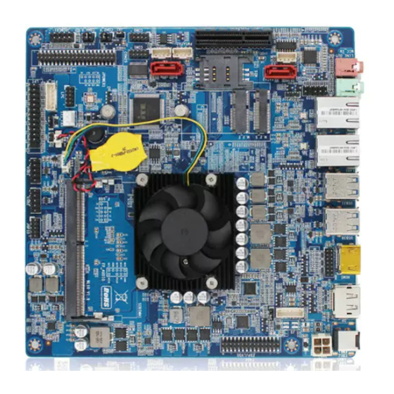
Maxtang WL10 User Manual V1.0 Chapter 1 Product Introduction 1.1 Brief Introduction The WL10 is based on the Intel Whiskey Lake-U platform. 1.2 Parameters Whiskey Lake-U platform i7-8565U--quad core, 1.8 GHz, TDP 15W, supporting Turbo Boost Technology and EIST i5-8265U--quad core, 1.6GHz, TDP 15W, supporting Turbo Boost Technology and EIST i3-8145U--dual core, 2.1GHz, TDP 15W, supporting Turbo Boost Technology and EIST... - Page 3 Maxtang WL10 User Manual V1.0 1.3 Connector Diagram HDMI DC_IN AUDIO LAN2 USB3.0 LAN1 PWR3 FP-AUDIO EDP/LVDS_ADJ JAUD SATA2 M.2_SSD/3G/4G BKADJ_C EDP/LVDS PCIEX4 M.2_WIFI PWSATA1 PWSATA2 SATA1 COM6 COM1 MEMORY COM2_P SYS_FAN COM4_P CPU_FAN JPOWER1 COM25 PS2_H USB2 USB1 JGPIO...
- Page 4 Maxtang WL10 User Manual V1.0 MEMORY...
-
Page 5: Chapter 2 Hardware
Maxtang WL10 User Manual V1.0 Chapter 2 Hardware 2.1 Jumper Setting Please configure the jumpers according to your requirements before installing the hardware. How to identify the first header of jumpers and pins: Observe the mark beside the jumper or pins and find the header marked by “1”... - Page 6 Maxtang WL10 User Manual V1.0 Display backlight brightness adjustment pin (screen printing: EDP/LVDS_ADJ) Signal LCD_BKL_ADJ LCD_BKL_ON LVDS display backlight two-way adjustment jumper (screen printing: BKLADJ_C) Settings Function Close Backlight control Close Backlight control Display power supply jumper (screen printing: J3)
- Page 7 Maxtang WL10 User Manual V1.0 Signal Signal EDP_AUXN EDP_AUXP EDP_DATA0_P EDP_DATA0_N EDP_DATA1_P EDP_DATA1_N eDP Display backlight brightness adjustment pin (screen printing: EDP/LVDS_ADJ) Signal LCD_BKL_ADJ LCD_BKL_ON eDP display backlight two-way adjustment jumper (screen printing: BKLADJ_C) Settings Function Close Backlight Close Backlight...
- Page 8 Maxtang WL10 User Manual V1.0 Interface Settings Function Close +3.3V Close Note: The eDP display power is controlled by jumpers. The voltage can be 5V or 3.3V. Don't short-circuit two or more interfaces with jumper cap. 2.6 HDMI pin (screen printing: JHDMI) The board is equipped with pin HDMI interface as backup option.
- Page 9 Maxtang WL10 User Manual V1.0 2.10 USB interface 3 standard USB3.0. 5 x USB2.0, 4 of them being USB2.0 pin on-board, the test one being rear USB2.0 port (screen printing: USB3.0) USB1 and USB2 (screen printing: USB1, USB2) Signal Signal...
- Page 10 Maxtang WL10 User Manual V1.0 Signal Signal F-IO-SEN(AGNG) (NC) FRO-L LIN2-JD JAUD (screen printing: JAUD) Signal SPDIF (screen printing: SPDIF) Signal SPDIF_Out 2.13 COM (screen printing: COM1, COM25, COM6, JCOM2_P, JCOM4_P) It is equipped with 6 COM (2.0mm spacing of built-in pins). COM1 slots are defined by industrial control;...
- Page 11 Maxtang WL10 User Manual V1.0 COM25 (screen printing: COM25) Signal Signal DCD# DTR# DSR# RTS# CTS# DCD# DTR# DSR# RTS# CTS# DCD# DTR# DSR# RTS# CTS# DCD# DTR# DSR# RTS# CTS# COM6 (screen printing: COM6) Signal Signal DATA- DATA+ (NC)
- Page 12 Maxtang WL10 User Manual V1.0 COM2_P, COM4_P (screen printing: COM2_P、COM4_P) Interfa Settings Function Close Close Close 2.14 LPT (screen printing: LPT) On-board 1 set of 2X13 pin LPT interface. The adapter cable is needed to transfer the LPT to the standard parallel interface for use.
- Page 13 Maxtang WL10 User Manual V1.0 2.15 GPIO pin (screen printing: GPIO) The board is equipped with a set of 2 x 5pin as JGPIO pin (2.0mm spacing), supporting 8 programmable I/O lanes in total. GPIO (screen printing: JGPIO) Signal Signal PCH_GPP_C16 3.3V...
- Page 14 Maxtang WL10 User Manual V1.0 PWR3: ATX12V supplementary power supply socket (2x2PIN) 2.18 Switch panel pin (screen printing: JPOWER1) The front control panel interfaces are to connect the functional buttons and indicators on the front panel. JPOWER1 (screen printing: JPOWER1)
- Page 15 Maxtang WL10 User Manual V1.0 Step 2: Use the jumper cap to connect the 1st and 2nd headers of JCMOS for about 10 seconds and disconnect; Step 3: When starting the device, press the <DEL> button to enter the BIOS, load the optimal default value and save and exit the settings.
Need help?
Do you have a question about the WL10 and is the answer not in the manual?
Questions and answers