
Related Manuals for Parker OEM750


Summary of Contents for Parker OEM750
- Page 1 OEM750 Drive OEM750X Drive/Indexer User Guide r i e R / F Compumotor Division Parker Hannifin Corporation p/n 88-016109-01 A...
- Page 2 KEEP CLEAR of these areas when power is applied to the equipment. Parker Compumotor constantly strives to improve all of its products. We reserve the right to modify equipment and user guides without prior notice. No part of this user guide may be reproduced in any form without prior consent from Parker Compumotor.
- Page 3 Electromagnetic Compatibility Directive 89/336/EEC. How- ever, information is offered in Appendix B, EMC Installation Guide on how to install the OEM750 and OEM750X in a manner most likely to minimize the effects of drive emissions and to maximize the immunity of drives from externally generated interference.
- Page 4 Features ........................4 2 INSTALLATION ............5 OEM750/OEM750X Ship kit ..................5 Quick Test ........................6 Quick Test: OEM750 with Separate Indexer .............. 13 Quick Test: OEM750X ....................14 DIP Switch Functions ....................16 OEM750 Inputs and Outputs ..................19 Step Input ......................
- Page 5 APPENDIX A: LVD INSTALLATION INSTRUCTIONS . 65 Environmental Conditions ................... 65 Electrical ........................65 Mechanical ........................67 Servicing the OEM750/OEM750X ................67 Thermal Safety ......................67 Sonic Pressure ......................67 Table of Graphic Symbols and Warnings ..............68 APPENDIX B: EMC INSTALLATION GUIDE ....69 General Product Philosophy ..................
- Page 6 This chapter contains information on identifying and resolving system problems. Descriptions of LED signals, debugging tools, problems/solutions table are included. Appendix A: LVD Installation Instructions This appendix contains information on installing the OEM750/OEM750X so that it complies with the Low Voltage Directive of the European Community.
- Page 7 OEM750 • Preface Appendix B: EMC Installation Guide This chapter contains information on how to install the OEM750/OEM750X so that the effects of drive emissions are minimized, and drive immunity to externally generated inter- ference is maximized. NSTALLATION REPARATION Before you install this product, complete the following steps: 1.
- Page 8 Preface • OEM750 Situations that may cause system damage are presented as cautions. Examples are shown below. WARNING Do not touch the motor immediately after it has been in use for an extended period of time. The motor may be hot.
-
Page 9: Introduction
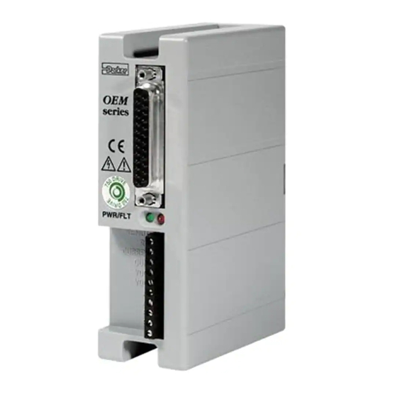
• Understand the product’s basic functions and features OEM750 Drive Description The OEM750 Drive is optimized to operate size 23 and 34 two- phase permanent magnet hybrid step motors. It is a high- performance module around which the Original Equipment Manufacturer (OEM) can design a motion control system. - Page 10 Introduction • OEM750 The OEM750 is small and convenient to use. It installs with only two screws; the screws also provide grounding and captivate the cover. Its right-angle screw terminal allows side- by-side mounting, and its small footprint maximizes cabinet space.
-
Page 11: Related Products
• Power Dump for Regeneration (requires a user-supplied external resistor) Related Products The OEM750 Drive has an internal slot where an indexer circuit board can be installed at the factory. The resulting product is referred to as an OEM750X. r i e... -
Page 12: Oem750X Drive/Indexer Description
The OEM750X Drive/Indexer is the same drive product as the OEM750, but it includes an indexer (position controller). The OEM750X is the same size as the OEM750 and it incorporates the same design technologies. The indexer uses commands from Compumotor’s popular and easy to use X Series Language. -
Page 13: Installation
The following option may be used with the OEM750X. Option Description Nonvolatile Memory (2k BBRAM) The following motor(s) may be used with the OEM750 and OEM750X. Compare your order with the motors shipped. Part Part Number Size 23—1/2 Stack Stepping Motor... -
Page 14: Quick Test
CAUTION The drive and motor should be mounted to a heatsink. Drive mounting does not affect the following tests, but operating the OEM750/OEM750X and motor for extended periods without proper mounting can cause the drive to fault due to overheating. Possible motor damage may occur. When you complete the quick tests, remove power to the drive. - Page 15 Alternating mode approximately 6 revolutions at 1 rps. If you are testing an OEM750 with a separate indexer, or an OEM750X, you will use the indexer to command the motor to turn; you will not use the automatic test function.
- Page 16 Installation • OEM750 5. Attach the motor (to A+, A-, B+, B-). Do not connect the motor to the load at this time. Compumotor OS Series (OEM size 23) motors may be wired in a series or parallel configuration. However, if you are using a 75VDC power supply (such as an OEM300), we recommend that you use a series configuration.
- Page 17 OEM750 • Installation Phase A PWR/FLT Windings REMOTE CURRENT DUMP Phase B VDC+ Black Windings VDC- White Green Motor Wiring: Size 34, OEM83 Motors – Parallel Wiring Phase A PWR/FLT Windings REMOTE Blue CURRENT DUMP Yellow Phase B VDC+ Windings...
- Page 18 (0.2 mH – 80 mH is acceptable). The next table shows resistor values that you must use to properly set motor current when using the OEM750/ OEM750X with a non-OS or non-RS Series motor. The drive can generate from 0.2 to 7.5 amps, determined by the motor current range DIP switches (SW3-#7...
- Page 19 18.2 kΩ 27.4 kΩ 5.90 kΩ 21.5 kΩ *NOTE: Current is specified in I , or peak amperes per phase. I is related to the = √2(I average current value, I , as follows: I OEM750/750X Resistor Selection for Motor Current...
- Page 20 Do not reverse VDC+ and VDC-. Reversing these connections can seriously damage the drive. If you are testing an OEM750 with a separate indexer, or an OEM750X, skip Step 8 below, and proceed to one of the next two sections.
-
Page 21: Quick Test: Oem750 With Separate Indexer
1. Complete steps 1 – 7 from the Quick Test , but turn DIP SW3-#3 ON to disable the automatic test function. 2. To connect a Compumotor indexer to the OEM750’s 25 pin D-connector, use the cable provided with the indexer. Plug the cable into the OEM750’s 25 pin D- connector. -
Page 22: Quick Test: Oem750X
6. After verifying that the motor moves CW and CCW, turn off power. Quick Test: OEM750X 1. Complete steps 1- 7 from the OEM750 Quick Test, but turn DIP SW3-#3 ON to disable the automatic test function. 2. Connect the OEM750X to an RS-232C communications device (i.e., computer, PLC, etc.). - Page 23 OEM750 • Installation CAUTION RS-232C signals are not on pins 2, 3, and 7 of the 25 pin D-connector. The next drawing shows the test configuration with an OEM750X and an RS-232C terminal. 14 Tx DANGER HIGH 15 Rx VOLTAGE...
-
Page 24: Dip Switch Functions
Installation • OEM750 DIP Switch Functions Configure the OEM750/OEM750X’s DIP switches for your motor and application. See Quick Test for switch location. The following table and descriptions summarize switch settings. OEM750 DIP SETTINGS Factory Default Con- figuration Shown SW 2... - Page 25 OEM750 • Installation Anti-Resonance SW2-#1 should be on for the anti-resonance circuit to be enabled. Normally, you will want anti-resonance to be en- abled; therefore, this switch should be on. If you are using pulse placement for positioning, you may need to disable anti- resonance.
- Page 26 Installation • OEM750 Current Loop Gain Set the current loop gain DIP switches to maximize your system’s performance. Your system has a gain. Its value is determined by three parameters: power supply voltage, motor inductance, and current loop gain. If you increase power supply voltage or decrease motor inductance, the system will have more gain.
-
Page 27: Oem750 Inputs And Outputs
Be sure that SW3-#7 and SW3-#8 are set to the proper current range for the resistor you installed. OEM750 Inputs and Outputs The next figure shows internal connections for the OEM750. See the following section for OEM750X internal connections. Internal Connections 243Ω... -
Page 28: Remote Input
Installation • OEM750 VDC. With no external current limiting resistor, the current is controlled by the applied voltage. This is due to a fixed voltage drop of 1.7VDC on the opto LED and the internal series resistor (243Ω). Increased voltage will result in increased current. -
Page 29: Fault Output
OEM750 • Installation CAUTION Reverse voltage in excess of 6VDC may damage this device. With no external current limiting resistor, the current is controlled by the applied voltage. This is due to a fixed voltage drop of 1.5VDC on the opto LED and the internal series resistor (681Ω). -
Page 30: Gear Shift Input
Installation • OEM750 The fault output has the following electrical characteristics: • = 70VDC • = 0.3VDC CESAT • Collector Current = 10 mA maximum • Dissipation = 55 mW maximum HIFT NPUT The gear shift input is an optically isolated input. The GS+ terminal (pin 11) is connected to the anode of the OPTO lead via a 681Ω... -
Page 31: Oem750X Inputs And Outputs
OEM750 • Installation OEM750X Inputs and Outputs The next drawing shows the pin-out for the OEM750X. Step Output Direction Output N.C. CW Limit Shutdown N.C. series CCW Limit Encoder Channel A N.O. Home Encoder Channel B Reserved Encoder Channel Z GND Ref. - Page 32 Installation • OEM750 Internal Connections External Devices ACTØ4 Step Output Drive, Oscilloscope, etc. Direction Output ACTØ4 • Minimum high level output: 4.26V (source 24mA) • Maximum low-level output: 0.44V (sinks 24mA) Step and Direction Outputs CW (P 3) & CCW (P...
-
Page 33: Output #1 And Output #2
OEM750 • Installation OSITION NPUT The OEM750X has one dedicated home input. The home input allows you to establish a home reference input. This input is not active during power-up—its default active state is low. Refer to the Go Home (GH) command for more informa- tion on setting up and using this function. -
Page 34: Dedicated Fault Output
Installation • OEM750 EDICATED AULT UTPUT The OEM750X has one dedicated fault output. This output may be used to signal peripheral devices if an OEM750X failure occurs. The Fault output's default state is logic high. If a fault occurs, internal circuitry energizes the transistor’s base, pulling the output low. - Page 35 OEM750 • Installation Sequences are executed remotely by using one of the following logic patterns. (1 represents a +5V signal, Ø represents a ØV signal.) Sequence # Ø SEQ Input #1 Ø Ø Ø Ø SEQ Input #2 Ø Ø...
-
Page 36: Shutdown Output
Installation • OEM750 HUTDOWN UTPUT The OEM750X produces a shutdown output that is identical to its own internal signal. This output may be used to slave to another drive or to monitor the OEM750X. The shutdown output's default state is logic high. The figure represents a typical configuration of this output. -
Page 37: Trigger Inputs #1 – #3
OEM750 • Installation A, B, Z (P 17–19) NCODER NPUTS The OEM750X has three dedicated inputs for use with a single ended incremental encoder. These inputs, in conjunc- tion with the FS commands, determine encoder functionality. Reference the encoder ground to pin 7 of the OEM750X. -
Page 38: Address Inputs #1 – #3
Installation • OEM750 #1 – #3 (P 23 – 25) DDRESS NPUTS The OEM750X has three dedicated address inputs that allow you to specify a unique address for each OEM750X in your configuration. Their default active state is high. External Devices... - Page 39 OEM750 • Installation series series series PWR/FLT PWR/FLT PWR/FLT REMOTE REMOTE REMOTE CURRENT CURRENT CURRENT DUMP DUMP DUMP VDC+ VDC+ VDC+ VDC- VDC- VDC- Daisy Chain Configuration Commands prefixed with a device address control only the drive specified. Commands without a device address control all drives on the daisy chain.
-
Page 40: Choosing A Power Supply
OTOR Compumotor’s OS and RS Series motors are custom-made for use with the OEM750/OEM750X. These motors are not available as a standard model from any other manufacturer. They are designed for low loss at rest and at high speed. -
Page 41: Power Dump
If you do not use an OS or RS motor, you should consult Compumotor's Applications Engineering Department for assistance (800-358-9070). The OEM750/OEM750X is designed to run 2-phase PM step motors only. Do not use variable reluctance or DC motors. URRENT... -
Page 42: Mounting
Installation • OEM750 Mounting The OEM750/OEM750X is designed for a minimum area mounting configuration. An optional heatsink can be used for a minimum depth mounting configuration. This surface must be thermally coupled to a 2x 0.177 (4.50) cold plate in most... -
Page 43: Panel Layout
Do not mount large, heat-producing equipment directly beneath the OEM750 or OEM750X. • Do not mount the OEM750 directly below an indexer or other heat sensitive equipment (the drive produces more heat than an indexer). • Fan cooling may be necessary. -
Page 44: Current (Amps)
P— Parallel Configuration *— operate 34 size motors in parallel only Power Dissipation The total thermal dissipation in the OEM750/OEM750X is almost constant, regardless of whether the motor is stationary or in motion. The current range DIP switches and the resistor that sets motor current determine the motor phase currents that cause the power losses shown in the figure above. - Page 45 25°C, active cooling (forced air) will be required to maintain the heatplate temperature below 55°C (131°F). Mount the OEM750/OEM750X to the OEM-HS1 heatsink with two #8-32 screws. (A heatsink with holes tapped for metric screws is available. Its part number is OEM-HS1-M4.
- Page 46 Installation • OEM750 1.175 (29.85) 2x #8-32 UNC-2B 0.200 4.650 (118.11) Thru One Fin (5.08) 0.175 2x Ø0.187 (4.75) Thru (4.45) 2x #8-32 UNC-2B Thru 0.637 (16.18) 4.650 (118.11) 0.175 0.450 (11.43) (4.45) 2.100 (53.34) 1.287 (32.69) 2.000 0.200 (5.08) 5.000 (127.00)
- Page 47 25°C, active cooling (forced air) will be required to maintain the heatplate temperature below 55°C (131°F). Mount the OEM750/OEM750X to the OEM-HS2 heatsink with two #8-32 screws. (A heatsink with holes tapped for metric screws is available. Its part number is OEM-HS2-M4.
- Page 48 Installation • OEM750 2.62 (66.55) 2x #8-32 UNC-2B Thru 0.37 (9.4) 1.175 2x Ø0.187 (4.75) Thru (29.85) 4.650 (118.110) 4.50 (114.3) 2.25 (57.2) 0.500 6.000 (152.40) Dimensions in inches (millimeters) (12.70) 7.000 (177.80) OEM-HS2 Dimensions 1 ( 2 5 . 4 )
-
Page 49: Motor Mounting
When a foot mount is used, for example, any radial load on the motor shaft is multiplied by a much longer lever arm. Motors used with the OEM750/OEM750X can produce very high torques and accelerations. If the mounting is inadequate, the high torque/high acceleration combination can shear shafts and mounting hardware. -
Page 50: Attaching The Load – Couplers
Installation • OEM750 Attaching the Load – Couplers Align the motor shaft and load as accurately as possible. In most applications, some misalignment is unavoidable, due to variations in component tolerance. However, excessive mis- alignment may degrade system performance. Three misalign- ment conditions, which can exist in any combination, are: •... -
Page 51: Tuning & Specifications
Mid-Range Instability All step motors are subject to mid-range instability. This instability, or oscillation, may stall the motor at speeds from 6 to 16 rps. The OEM750/OEM750X includes active circuitry to help suppress these oscillations. This feature is normally... -
Page 52: Tuning Procedure
Functions in Chapter 2) if it has an adverse effect on your system. Tuning Procedure Tuning on the OEM750/750X consist of two different aspects. The first is a current loop gain adjustment designed to match the drive's current compensation gain to the motor's induc- tance and the motor supply voltage. - Page 53 OEM750 • Tuning & Specifications ETERMINING OTOR ESONANCE There are several methods you can use to determine the level of motor resonance in your system. Tachometer Method Use an oscilloscope to gauge the output of a tachometer attached to the motor shaft. The tachometer will output a DC voltage, proportional to speed.
-
Page 54: Adjusting Motor Current Waveforms
Tuning & Specifications • OEM750 UNING THE RIVE TO THE OTOR To tune your drive to your motor, follow these directions: 1. Command the drive (via RS-232C or STEP & DIRECTION inputs) so that the motor is running at maximum roughness, as shown below for the 1st speed motor resonance. -
Page 55: Performance Specifications
UMBER ROSS EFERENCE ABLE When Compumotor introduced the OEM750/OEM750X, we changed the part numbering system for some existing motors, and introduced several new motors. The next table summa- rizes the changes and additions. (The letters “n” represent variables that can change, based upon the options ordered.) -
Page 56: Speed/Torque Curves
Tuning & Specifications • OEM750 PEED ORQUE URVES Speed/torque curves are shown below for operation at 24VDC, 48VDC, and 75VDC. Series and parallel curves are shown for 23 frame size motors. Parallel curves only are shown for 34 frame size motors. (OEM83 motors are internally wired in parallel and can only be operated in parallel.) - Page 57 400 (2.84) Parallel 136 (0.97) 320 (2.27) Parallel (6.9A pk) Parallel 102 (0.72) 240 (1.70) (7.5A pk) Series 68 (0.48) 160 (1.14) Series (3.8A pk) 34 (0.24) 80 (0.57) Parallel = Torque Speed-RPS Speed-RPS = Power OEM750/OEM750X Speed/Torque Curves at 48VDC...
- Page 58 Tuning & Specifications • OEM750 OEM750 with OS2HA OEM750 with or OEM57-40 Motors RS31B or OEM83-62 Motors Power Power (@75 VDC) (@75 VDC) oz-in (N-m) oz-in (N-m) (Watts) (Watts) (0.35) (1.06) Parallel Parallel (5.3A pk) 40 (0.28) 120 (0.85) 30 (0.21) 90 (0.64)
- Page 59 OEM750 • Tuning & Specifications —23 F OTOR PECIFICATIONS RAME OS2HA OS21A OS22A (OEM57-40) (OEM57-51) (OEM57-83) Static Torque oz-in (Nm) (0.26) (0.47) (0.94) Rotor inertia oz-in 0.38 0.65 1.39 (kg-cm (0.07) (0.12) (0.25) Drive current—Series 2.65 (Arms) (1.9) (2.3) (2.7) Drive current—Parallel...
- Page 60 Tuning & Specifications • OEM750 —34 F OTOR PECIFICATIONS RAME OEM83-62 OEM83-93 OEM83-135 RS31B RS32B RS33B Static Torque oz-in (Nm) (1.14) (2.14) (2.80) (1.03) (2.02) (2.55) Rotor inertia oz-in 3.47 6.76 10.47 3.204 6.563 9.652 (kg-cm (0.634) (1.24) (1.91) (0.583) (1.195)
- Page 61 OEM750 • Tuning & Specifications OTOR IMENSIONS Flexible boot may be bent as 13.5 shown. Nominal (343) 0.25 height 1.0 (25.4). Min. (6.4) 0.200 (5.08) dia (4) 0.2500 (6.350) on 2.625 (66.68) BC 0.2495 (6.337) Shaft Dia (25.4) 1.06 (26.9) 45°...
- Page 62 Tuning & Specifications • OEM750 0.0000 0.003 ( 0.077 ) -A- Ø.3750 3.38 0.0005 Motor leads (FLY) (85.85) L max. 0.000) (9.53 or with 10 ft cable 0.013) (R10) 0.002 ( 0.051 ) 2 x 45° Frame Size 34 0.06 (1.52) Model L max.
-
Page 63: Encoder Specifications
OEM750 • Tuning & Specifications Encoder Specifications NCODER IMENSIONS 18.0 (457) Mininimum 1.63 2.50 (41.4) (63.5) 0.72 (18.3) maximum 0.79 (20.1) 3.57 (90.68) 0.71 (18.0) Dimensions in inches (millimeters) HJ Encoder (OEM-E57) EC Encoder (OEM-E83) Dimensions – HJ (OEM-E57) and EC (OEM-E83) Encoders... - Page 64 Tuning & Specifications • OEM750...
-
Page 65: Troubleshooting
OEM750 • Troubleshooting C H A P T E R Troubleshooting Chapter Objectives The information in this chapter will enable you to: • Maintain the system to ensure smooth, efficient operation • Isolate and resolve system problems Drive Maintenance Ensure that the drive's heatplate has proper thermal contact with the mounting surface. -
Page 66: Problem Isolation
Troubleshooting • OEM750 Problem Isolation When your system does not function properly (or as you expect it to operate), the first thing that you must do is iden- tify and isolate the problem. When you accomplish this, you can effectively begin to resolve and eradicate the problem. -
Page 67: Front Panel Leds
OEM750 • Troubleshooting RONT ANEL The OEM750/OEM750X has two LEDs on its front panel. series Green POWER LED PWR/FLT REMOTE Red FAULT LED CURRENT DUMP VDC+ VDC- LEDs The FAULT LED is red and illuminates when the amplifier is disabled. This LED is activated when any of the following conditions occur: •... - Page 68 Troubleshooting • OEM750 Symptoms Probable Causes Solutions The drive loses Indexer is overdriving step input Verify that the step input current pulses at high is not greater than 15 mA speed Indexer is underdriving step Verify that the step input current input is greater than 6.25 mA...
- Page 69 Issue an XT command at the end appear to not be never issued XT, the of the sequence to end sequence responding to OEM750/OEM750X still thinks definition commands you are defining a sequence OEM750X may be off-line (F Issue an E command to bring the...
-
Page 70: Testing The Motor
Troubleshooting • OEM750 Symptoms Probable Causes Solutions Check for miswiring − carefully The motor fault The drive has detected a short LED is on circuit in the motor wiring check the motor wires for loose strand\s shorting the windings The drive is overheating Verify that the drives heatsink does not exceed 55 °C... -
Page 71: Rs-232C Problems
You should receive the echoed character. If not, consult the manufac- turer of the host’s serial interface for proper pin outs. Software Debugging Tools The OEM750/OEM750X has several tools that you can use to debug a problem in the system. The software tools are listed below:... -
Page 72: Returning The System
3. In the USA, call your Automation Technology Center (ATC) for a Return Material Authorization (RMA) number. Returned products cannot be accepted without an RMA number. If you cannot obtain an RMA number from your ATC, call Parker Compumotor's Customer Service Department at (800) 722-2282. -
Page 73: Electrical
The OEM750/OEM750X is designed for installation category II. LECTRICAL Connecting and Disconnecting Power The OEM750/OEM750X's protective earth connection is provided through its heatsink. You must reliably earth the OEM750/ OEM750X's protective earth connection. Attach or remove the OEM750/OEM750X's power connections only while input power is OFF. - Page 74 Use a ring terminal in combination with a star washer to make good contact with the exposed metal surface surrounding one of the OEM750/OEM750X’s mounting holes. (The dimension draw- ing in Chapter 2 indicates the mounting hole that has exposed metal.)
-
Page 75: Mechanical
Follow the motor manufacturer’s installation instructions. ECHANICAL Installing in an Enclosure The OEM750/OEM750X must be installed within an enclosure. The enclosure’s interior must not be accessible to the operator. The enclosure should be opened only by skilled or trained service personnel. -
Page 76: Table Of Graphic Symbols And Warnings
LVD INSTALLATION INSTRUCTIONS • OEM750/OEM750X Table of Graphic Symbols and Warnings The following symbols may appear in this user guide, and may be affixed to the products discussed in this user guide. Symbol Description Earth Terminal Protective Conductor Terminal Frame or ChassisTerminal... -
Page 77: Appendix B: Emc Installation Guide
It may be necessary to take additional measures in certain circumstances and at specific locations. Although these recommendations are based on expertise acquired during tests carried out on the OEM750/OEM750X, it is impossible for Compumotor to guarantee the compliance of any particular installation. Compliance will be strongly influenced by the physical and electrical details of the instal- lation and the performance of other system components. -
Page 78: General Considerations
This is usually achieved by fitting an isolator switch to the door assembly. The OEM750/OEM750X must be mounted to a conductive, earthed panel. If this has a paint finish, it will be necessary to remove the paint in certain areas where speci- fied. -
Page 79: Control Signal Connections
They therefore act as a lossy element in this waveband. The recommended components are produced by Parker Chomerics (617-935-4850) and are suitable for use with cable... - Page 80 EMC INSTALLATION GUIDE • OEM750/OEM750X having an outside diameter up to 10 – 13mm. The specifica- tion is as follows: Chomerics part number 83-10-M248-1000 83-10-A637-1000 Outside diameter 17.5mm (0.69 in.) 28.5mm (1.12 in.) Inside diameter 10.7mm (0.42 in.) 13.77mm (0.54 in.) Length 28.5mm (1.12 in.)
- Page 81 OEM750/OEM750X • EMC INSTALLATION GUIDE When installing an R-clamp, as shown in the next figure, install it as close to the cable end as possible. Mount the R- clamp to a suitable ground, backplane, earth stud or bus bar—this may require removing paint from a cabinet or panel.
-
Page 82: Oem Series Products
EMC INSTALLATION GUIDE • OEM750/OEM750X OEM Series Products Applicable Products: OEM750, OEM750X, OEM300, OEM1000 Please read this section in conjunction with the general considerations applicable to all products. XTERNAL NCLOSURE Before mounting the drive, ensure that the mounting location is flat and free from paint or other non conductive surface coatings, if necessary remove paint from the corresponding mounting area. - Page 83 (see the next figure). Take the power supply earth connection from the same stud that retains the filter case earth. Attach the DC power supply output to the OEM750/ OEM750X, using 2-core 1.5mm (AWG 14) (SWG 16) twisted wiring, as shown in the next figure.
-
Page 84: Motor Cabling
OTORS EMOVABLE ABLING Except for the C10 cabling option of the RS motors, Parker Compumotor OEM Series drive/motor systems ship with motors that do not incorporate braided screen. (Applicable motors are OS Series, RS Series with the L10 option, and OEM Series motors.) - Page 85 OEM750/OEM750X • EMC INSTALLATION GUIDE OEM Series Drive Remove paint behind mounting plates o to i e s s e r Power Supply (OEM300 Shown) r i e o to Braided-screen 2 .7 cables two-wire H IG twisted pair 0 -2...
-
Page 86: Motor Cables
EMC INSTALLATION GUIDE • OEM750/OEM750X RS S C10 O OMPUMOTOR ERIES OTOR WITH PTION The C10 option for Compumotor’s RS Series motors includes a removable braided cable and all necessary hardware for making an EMC compliant installation. At the motor end of the motor cable, follow the installation instructions that are included with the C10 cable kit. - Page 87 OEM750/OEM750X • EMC INSTALLATION GUIDE OEM Series Drive Remove paint behind mounting plates o to i e s s e r Power Supply (OEM300 Shown) Green/Yellow Safety Earth Conductor AC Input must be terminated Filter (see r i e to system earth point...
-
Page 88: Motors
EMC INSTALLATION GUIDE • OEM750/OEM750X stable manner is difficult because the screen itself is com- paratively fragile - bending it in a tight radius can seriously affect the screening performance. There must be no break in the 360° coverage that the screen provides around the cable conductors. -
Page 89: Communications
IGNAL IRING High-quality braided screen cable should be used for control connections. In the case of the OEM750/OEM750X, which has differential step/direction inputs, it is preferable to use cable with twisted pairs to minimize magnetic coupling. I/O lines require that separate grounds be individually run for each I/O point. - Page 90 EMC INSTALLATION GUIDE • OEM750/OEM750X...
-
Page 91: Index
OEM750 • INDEX Index earth 65 absorbers 71 Electromagnetic Compatibility AC supply filtering 70 Directive i, 69 accessories 6 EMC cable connections 76 accuracy 47 EMC installation instructions 69 address inputs 30 emissions 70 anti-resonance 17 enclosures 35, 70 attaching the load 42... - Page 92 INDEX • OEM750 inputs and outputs inputs and outputs 23 OEM750 19 quick test 14 OEM750X 23 options instability 43 -M2 5 installation high current heatsink, OEM- EMC 69 HS2 6, 39 LVD 65 low current heatsink, OEM- installation category 65...
- Page 93 OEM750 • INDEX sequence inputs 26 series motor wiring 8 shaft modifications 41 ship kit 5 shutdown output 28 sine wave current waveform 46 single-flex coupling 42 sinusoidal current waveforms 46 smoothness 45 software debugging 63 Software Reference Manual v...
- Page 94 INDEX • OEM750...
- Page 95 OEM750 DIP SETTINGS Factory Default Con- figuration Shown SW 2 SW 3 Anti-resonance Anti-res. Disabled Default Anti-res. Enabled Resolution 50,800 50,000 (Steps per Revolution) 36,000 25,600 25,400 Default Setting 25,000 21,600 20,000 18,000 12,800 10,000 5,000 2,000 1,000 Waveform Pure Sine...
- Page 96 Fault Output Gear Shift Input ILD213 10kΩ BS170 ILD213 681Ω 25 Pin D-Connector Mounted on OEM750 OEM750 Inputs & Outputs, and Internal Connections 25 Pin D-Connector Mounted on OEM750X Step Output Direction Output N.C. CW Limit Shutdown N.C. CCW Limit...
Need help?
Do you have a question about the OEM750 and is the answer not in the manual?
Questions and answers