
Related Manuals for Regulus LYRA 1000 DVS


Summary of Contents for Regulus LYRA 1000 DVS
- Page 1 Installation and Operation Manual LYRA 1000 DVS THERMAL STORE LYRA 1000 DVS │...
-
Page 2: Table Of Contents
Models ....................Tank protection ................. Thermal insulation ................Packaging ..................General Information .................. Technical Data and Dimensions of Regulus LYRA 1000 DVS ....Operation ....................Connection ....................Mounting pump stations and accessories onto ........ Connecting heating circuits .............. Connecting a DHW circuit .............. -
Page 3: Description
1 Description Regulus LYRA Thermal Stores are intended for accumulation and subsequent distribution of thermal energy from solid-fuel fi red boilers, heat pumps, solar collectors, electric boilers etc. The Thermal Store shall be always connected to a sealed heating circuit. -
Page 4: Technical Data And Dimensions Of Regulus Lyra 1000 Dvs
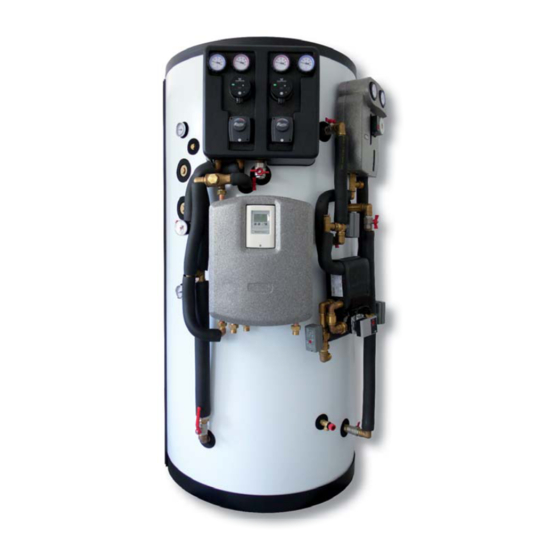
3 Technical Data and Dimensions of Regulus LYRA 1000 DVS codes VIEW A Total fl uid volume in tank ....................925 l Max. working temperature in tank ..................95 °C Max. working pressure in tank ................... 4 bar Hot water recovery rate from 10 °C to 50 °C with 63 °C heating water temp....1800 l/h (84kW) Empty weight ........................ -
Page 5: Connection
5.1 Mounting pump stations and accessories onto SCOPE OF SUPPLY Regulus LYRA Thermal Store, code 13181 (the other thermal stores, codes 13184 and 13421, differ only in the number of heating circuits, or in the option to connect recirculation to the fresh water station, or in the pool heating option). - Page 6 13234 - CONNECTION KIT FOR TSV ASSY Code Item name 11946 DN20 Pipe for water, 65-125 mm long, 3/4“ F and M threads 1 pcs Ball Valve 3/4“ M/F, red butterfl y handle 1 pcs 6970 3/4“ M/M brass hex nipple 1 pcs 13237 - ACCESSORY KIT Code...
- Page 7 MODELS FOR A POOL 13421 - LYRA 1000 DVS FOR A POOL Code Item name 13171 PS1000 FWS DV Thermal Store for LYRA DV 1 pcs 13172 Insulation for PS1000 FWS DV Thermal Store code 13171, NEODUL 1 pcs 12224 Pump station for Thermal Store –...
- Page 8 MOUNTING INSTRUCTIONS WARNING! At least 20°C and 4 persons are necessary to mount the insulation. All threaded connections shall be sealed either with a thread sealant or with the gaskets included in separate kits. 1. Remove the tank from its pallet and place it to its approximate position, shift the bottom insulation under the tank.
- Page 9 4. Peel off the protective foil from the insulation, apply the self-adhesive annuluses around the openings for connections. Some annuluses are cut out, these shall be used in places where openings are close to each other (the annuluses overlap). 5. Fit the Angled Ball Valve Assy (code 12690). From this point on, it is important to stick to the sequence of installation steps described below! │...
- Page 10 6. Fit the Pressure Gauge Assy (code 12689). 7. Fit the plug (code 7691) into the 1” sleeve below the Pressure Gauge Assy. │...
- Page 11 8. Fit the 3/4“ brass hex nipple (code 6970) into the sleeve, and the ball valve (code 998, included in Kit 13234) onto the nipple. Turn the ball valve into a position shown in the Fig. 9. Fit the Ball Valve & Elbow Assy (code 13236) into the lower 1” sleeve. │...
- Page 12 10. Fit the metal sheet against the four pins and fi x it using 4 screws M6x16 with washers (codes 12996 and 7853, included in Kit 12226). Also place insulation washers under and on the metal sheet and loosen the clamps. Fit the Pump Station with 4-way mixing valves (code 12224 or 12225).
- Page 13 12. Using the ¾” pipe 100 mm long (code 11946, included in Kit 13234), connect the TSV3 Assy (code 12687) with the ¾” ball valve (see Point 8). Prior to assembly, cut the insulation and slide it onto the pipe. 13.
- Page 14 15. Using the 1” pipe, 250 mm long (code 3016), connect the Manometer Assy with the inner elbow of the pump station with 4-way valves. 16. Fit the 1” pipe, 410 mm long (code 11271) to the pump station. 17. Fit the ¾” pipes 320 and 450 mm long (code 3014) to the T-Piece Assy (code 13983). The 450 mm long pipe shall be fi...
- Page 15 18. Connect the T-Piece Assy at 3 points, see Fig. 19. Using the 5/4” pipe, 580 mm long (code 13984), connect the T-Piece Assy with the Ball Valve Assy. │...
- Page 16 20. Fit two thermometers (code 10474, included in Kit 13237), 6/4“ and 1/2“ plugs or electric heating elements and a safety thermostat. 1/2” plug or safety thermostat 6/4” plugs or THERMOMETERS electric heating elements 21. Stretch the pipes to their preliminary lengths, cut the insulation and slide it onto the pipes: Model for a pool (included in Kit 13951): - 1 pipe 1”...
- Page 17 22. Fit the Ball Valve Assy for upper return (code 13270). 23. Fit the 1” M to 3/4” F reducing piece (code 7223, included in Kit 13451 or 13951) onto the solar pump station (code 14866) below the pump. Model for a pool: Fit the Pool Inlet Assy (code 13269) as shown in the fi gure. Model with no pool: Fit the Plate HE Inlet Assy (code 13275) as shown in the fi...
- Page 18 24. Fit the solar pump station (code 14866) using 2 M6x16 bolts with washers (codes 12996 and 7853, included in Kit 13451 or 13951). 25. Fit the Ball Valve Assy for tanks with a plate HE (code 13263). │...
- Page 19 26. Fit the plate heat exchanger support (code 13438, included in Kit 13452) using 2 bolts M8x18 with washers (codes 7259 and 7008), put washers under the support and then also onto the support. 27 Fit the hex nipple (code 6971) into the sleeve fi rst, and then the safety valve (code 605, included in Kit 13237).
- Page 20 28. Fit the Ball Valve Assy for lower return (code 13265). 29. Fit the Zone Valve Assy for DV outlet (code 13268). │...
- Page 21 30. Fit the Connection Assy - zone valve to DV (code 13267). 31. Model for a pool: Remove the last part of the radiator fi tting from the Zone Valve Assy (code 13272) and screw it to the plate heat exchanger as shown below. Model with no pool: Screw the fi...
- Page 22 32. Fit the 3/4” FF elbow (code 10192, included in Kit 13452) to the plate heat exchanger. 33. Fit the Assy for circulation pump connection (code 13266) to the plate heat exchanger. │...
- Page 23 34. This point applies to models with pool only: Fit the rest of the Pool Zone Valve Assy (code 13272). 35. Model for a pool: Using the 1” pipe 1000 mm long (code 13952), connect the solar pump station reducing piece with the AB port of the zone valve, see fi g. │...
- Page 24 Model with no pool: Using the 1” pipe 1250 mm long (code 13447), connect the solar pump station reducing piece with the plate heat exchanger, see fi g. 36. Using the 3/4” pipe 500 mm long (code 3041), connect the plate heat exchanger elbow with the solar pump station, see fi...
- Page 25 37. Using the 3/4” pipe 200 mm long (code 3012), connect the plate heat exchanger to the Assy for connecting a zone valve. 38. Fit the pump (code 12128) to the Assy for connecting a circulation pump. The fl ow direction is into the heat exchanger (the arrow pointing left).
- Page 26 39. Fit the Zone Valve Assy (code 13264) to the pump. The port B of the zone valve shall be oriented upwards! 40. Using the 1” pipe 460 mm long (code 13448), connect the zone valve with the ball valve. │...
- Page 27 41. Using the 1” pipe 360 mm long (code 13449), connect the zone valve with the ball valve. 42. Using the 1” pipe 330 mm long (code 13450), connect the zone valve with the ball valve. Fit the actuators onto the zone valves. │...
- Page 28 43. Push the front and top insulation onto the pump station with 4-way valves (codes 12223 and 12720). 44. Connect the terminals of the pumps, push the cables behind the insulation. 45. Fit the plastic cover onto the pump station with 4-way valves and fix it with 4 plastic screws M6x10 (code 12713).
- Page 29 46. Put the top insulation and plastic cover onto the tank. 47. Fit the automatic air release valve (code 11708) with the ball valve (code 11965) and fitting (code 6971, all included in Kit code 13237). │...
- Page 30 Completely fi tted tank: │...
-
Page 31: Connecting Heating Circuits
5.2 Connecting heating circuits 1. Return line from Heating Circuit 1 – G1”F 2. Flow to Heating Circuit 1 – G1”F 3. Flow to Heating Circuit 2 – G1”F 4. Return line from Heating Circuit 2 – G1”F 5.3 Connecting a DHW circuit 1. -
Page 32: Examples Of Heat Source Connection
5.5 Examples of heat source connection Inlets and outlets for connecting heat sources are located opposite the heating pump station. EXAMPLE I: Fireplace insert with hydronic heat exchanger and a hydronic heating boiler (electric-, gas-, oil- or pellet-fired). electricity boiler pellets fireplace insert with hydronic heat... -
Page 33: Fitting Electric Heating Elements
EXAMPLE III. Heat pump with max. flow temperature over 60°C, el. heating elements safety thermostat el. heating elements heat pump 65 °C max. flow temp. Expansion Vessel Connection Kit (code 13437) 5.6. Fitting electric heating elements The Thermal Store can be fitted with up to 2 electric heating elements of max. 12 kW total power output. The G6/4” sleeves, located in the middle of the tank below the heating pump station, are intended for these elements. -
Page 34: Installation And Commissioning
6 - Installation and Commissioning Installation shall meet valid rules and may be done by qualified staff only. El. heating elements shall be wired by qualified staff only. Defects caused by improper installation, use or handling are not covered by warranty. After the tank is installed and connected to an existing heating system, it is recommended to clean the entire heating system using a suitable cleaning agent, e.g. - Page 35 │...
- Page 36 ©2017 We reserve the right to errors, changes and improvements without prior notice. REGULUS spol. s r.o. E-mail: sales@regulus.eu Web: www.regulus.eu...
Need help?
Do you have a question about the LYRA 1000 DVS and is the answer not in the manual?
Questions and answers