Table of Contents
Advertisement
Advertisement
Table of Contents

Subscribe to Our Youtube Channel
Related Manuals for DAD PX Series


Summary of Contents for DAD PX Series
- Page 1 PX1000 PX2000 PX3600+ PX5000+ USER MANUAL...
-
Page 3: Table Of Contents
& 2 1 7 ( 1 7 6 Contents................................3 Important precautions............................4 Safety instructions............................5 FXQFW L RQ ' HVFU L SW L RQ............................6 Introduction..............................6 Front panel...............................6 Front panel function description ........................7 Rear panel...............................8 Rear panel function description...........................9 Reliability - Protection functions........................11 Factory settings...........................11 Installation and operation manual........................12 System connection............................12... -
Page 4: Important Precautions
IMPORTANT PRECAUTIONS 1. Read all documentation before using your equipment and save it for further reference. 2. Voltage must be correct and the same as that printed on the rear of the unit. Damage caused by connection to improper AC voltage is not covered by any warranty. 3. -
Page 5: Safety Instructions
SAFETY INSTRUCTIONS: Read safety instructions thoroughly before using the amplifier. Install equipment as follows: -- Install it on a flat surface, not bending or curved. -- Do not install it near water or moisture. -- Place power amplifier away from heat sources, such as radiators or other heat sources. Keep in mind the following rules when connecting amplifiers -- Read the user manual thoroughly... -
Page 6: Fxqfw L Rq ' Hvfu L Sw L Rq
) 8 1 & 7 ,2 1 ' ( 6 & 5 ,3 7 ,2 1 Introduction: 1. This amplifier employs new 3 steps class H power supply circuit, that makes the RMS output power higher, the operation temperature lower and the product's stability and reliability better. (Only for PX3600+/PX5000+) 2. -
Page 7: Front Panel Function Description
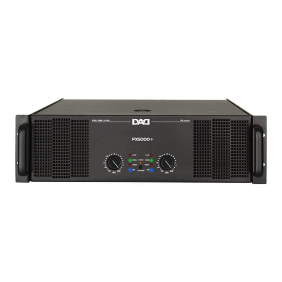
PX Series front panel function description: 1. Handle Please use this handle to transport the amplifier. 2. Air Entrance This part isfor the air entrance. Don't obstruct it. 3. "CLIP" LED When this indicator lights up, it shows that the output signal reaches the peak, and causes clipping. -
Page 8: Rear Panel
PX1000-PX2000 rear panel CH1 /BRIDGE OUTPUT SPEAKON 1: STEREO:1+/1- BRIDGE:1+/2+ T8AL 250V ~230V/50Hz 900W PX3600+-PX5000+ rear panel CH1/BRIDGE CH1 INPUT CH1 LINK OUTPUT SPEAKON 1: BRIDGE MODE STEREO:1+/1- BRIDGE:1+/2+ OPERATION SENSITIVITY MODE 0.775V BRIDGE 1.0V PARALLEL CAUTION: 1.4V STEREO REPLACE ONLY WITH SAME TYPE FUSE! 30Hz HI-PASS... -
Page 9: Rear Panel Function Description
PX1000-PX2000 rear panel function description: 1. Channel 1 XLR Input This XLR input is a balanced input. 2. Channel 1 Link Socket This balanced socket is used to link another amplifier. 3. Input Sensitivity Selector This selector allows to choose the input sensitivity among: 0.775V, 1.0V or 1.4V. 4. - Page 10 PX3600+-PX5000+ rear panel function description: 1. Channel 1 XLR Input This XLR input is a balanced input. 2. Channel 1 bypass socket It provides the same output signal as the input 1signal. 3. Input Sensitivity Selector Please use this selector to choose input sensitivity among: 0.775V, 1.0V or 1.4V. Operation Mode Selector Please use this switch to choose among the power amplifier operating modes: - Stereo Mode: the two channels are completely independent.
-
Page 11: Reliability - Protection Functions
Reliability - Protection function This amplifier has many protecting functions that give to this product a great reliability. These protections prevent damages either to amplifier or to loudspeakers. 1. Clip / limiter When the amplifier output appears to be clipped, to avoid damages to the speakers, a built-in clip/limiter automatically limits too high input signals. -
Page 12: Installation And Operation Manual
1.1 While unpacking the package, please check all the provided accessories along with the equipment status. Usually, it is better save all packing materials. 1.2 PX series cases are designed to fit 2 or 3 standard 19” rack units and are provided with standard fixing holes on both front and rear panel. -
Page 13: Basic Operation
2. Basic operation 2.1 Switching on It is opportune to turn channel 1 & 2 volume controls all the way down (-80dB) before switching the amplifier on. After having inserted the plug into the power outlet, the devices goes in the stand-by mode, and is ready to work. -
Page 14: Connection Modes And Settings
3. Connection modes and settings 3.1 PX1000-PX2000 stereo mode STEREO CH1 /BRIDGE OUTPUT SPEAKON 1: STEREO:1+/1- BRIDGE:1+/2+ T8AL 250V ~230V/50Hz 900W In this mode, connect the CH1 and CH2 inputs to your mixer s outputs. Put the selector on the “Stereo” position. Output volume can be adjusted by means of the two potentiometers. - Page 15 Bridge mode: BRIDGE CH1 /BRIDGE OUTPUT SPEAKON 1: STEREO:1+/1- BRIDGE:1+/2+ T8AL 250V ~230V/50Hz 900W In this mode, connect the input CH1 to your mixer s outputs. Put the selector on the “Bridge” position. Output volume can be adjusted by means of the channel 1 potentiometer.
- Page 16 Parallel mode (OUT) (IN) Parallel CH1/BRIDGE CH1 INPUT CH1 LINK OUTPUT SPEAKON 1: BRIDGE MODE STEREO:1+/1- BRIDGE:1+/2+ OPERATION SENSITIVITY MODE 0.775V BRIDGE 1.0V PARALLEL CAUTION: 1.4V STEREO REPLACE ONLY WITH SAME TYPE FUSE! 30Hz HI-PASS 150Hz LO-PASS PIN 1 = PIN 2 = PIN 3 = LIMITER...
-
Page 17: Maintenance
Maintenance 1 Application range 1.1 This user manual is suitable only for DAD manufactured PX Series products. 1.2 PX amplifiers are suitable for live performances, band performances, discos, night clubs, etc... 2 Use circumstances 2.1 The room temperature shall be kept around 25 degree while used indoor. It can't be used in high temperature environments as over heating may cause damages to components. -
Page 18: Schematic Diagram
Schematic diagram (Only for PX3600+/PX5000+) -
Page 19: Packing List
Packing list PX1000-PX2000: Power amplifier x 1 unit / L QH FRU G x 1pcs User manual x 1pcs PX3600+-PX5000+: Power amplifier x 1 unit User manual x 1pcs... -
Page 20: Specifications
Speci cations 1. Technical Data MODEL PX1000 PX2000 PX3600+ PX5000+ ITEM 8 Ohm stereo power 250Wx2 520Wx2 800Wx2 1300Wx2 (RMS/THD1%) 4 Ohm stereo power 375Wx2 780Wx2 1200Wx2 1950Wx2 (RMS/THD1%) 2 Ohm stereo power 450Wx2 936Wx2 1600Wx2 2600Wx2 (EIA/THD1%) 4 Ohm bridge power 900W... -
Page 21: Measures
2. PX1000-PX2000 dimensions Front panel 89mm 483mm Rear panel CH1 /BRIDGE OUTPUT SPEAKON 1: STEREO:1+/1- BRIDGE:1+/2+ T8AL 250V 89mm ~230V/50Hz 900W 432mm... - Page 22 3. PX3600+-PX5000+ dimensions Front panel 133mm 483mm Rear panel CH1/BRIDGE CH1 INPUT CH1 LINK OUTPUT SPEAKON 1: BRIDGE MODE STEREO:1+/1- BRIDGE:1+/2+ OPERATION SENSITIVITY MODE 0.775V BRIDGE 1.0V PARALLEL CAUTION: 1.4V STEREO REPLACE ONLY WITH SAME TYPE FUSE! 30Hz HI-PASS 150Hz LO-PASS 133mm PIN 1 = PIN 2 =...
Need help?
Do you have a question about the PX Series and is the answer not in the manual?
Questions and answers