Table of Contents
Advertisement
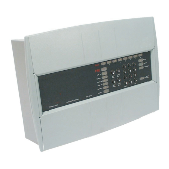
Data, Installation and Commissioning guide
Fire Control and Repeat panels
(Conventional 1, 2, 4 and 8 Zone panel range)
This manual covers a range of
conventional fire panel and include
system design, installation and
configuration information.
The fire panels covered are
designed in accordance with the
requirements of EN54 Part 2:1997
+ AMD 1 (and include optional
clauses 7.8, 7.10 & 7.11), plus the
requirements of EN54 Part 4:1997
+ AMD 1 and AMD 2.
This publication covers the
Conventional fire alarm panels:
q 1 zone panel:- 13270-01LB and
75585-01NMB
q 2 zone panel:- 13270-02LB and
75585-02NMB
q 4 zone panel:- 13270-04LB and
75585-04NMB
q 8 zone panel:- 13270-08LB and
75585-08NMB
q Fire alarm repeat panel:
13271-08LB and 75586-08NMB.
The panels are supplied without
batteries.
4188-424 issue 4_Part 1_10-09
This manual is intended
for use by installers and
commissioning engineers.
A separate Operating
instructions and Log book
has been supplied along
with this booklet which
must be forwarded on to
the End User.
Content
System design · · . . . . . 2
Cables - · · · · · . . . . . 4
Notes to installers . . . . . 5
Panel fixing· · · · . . . . . 6
Terminals · · · · . . . . . 8
Controls & indicators . . . . 9
Power up tests · · . . . . . 10
Installed system tests . . . 11
Config. considerations . . . 11
Access levels 2 · . . . . . 12
Access level 2 functions . . 12
Programming Options . . . 14
Access level 3 functions . . 14
Access level 4 functions . . 15
Fault indications · . . . . . 16
Fault finding · · · . . . . . 17
Control panel· · · . . . . . 20
Repeat panel· · · . . . . . 22
Parts list · · · · · . . . . . 23
Page
Advertisement
Table of Contents

Related Manuals for Honeywell 13270-01LB


Summary of Contents for Honeywell 13270-01LB
-
Page 1: Table Of Contents
This publication covers the Operating instructions for Conventional fire alarm panels: Access level 2 functions . . 12 q 1 zone panel:- 13270-01LB and Programming Options . . . 14 Operating instructions for 75585-01NMB Access level 3 functions . . 14... -
Page 2: System Design
System design Fire Panels System design NOTE: Spur wiring is not permitted off zone circuits. End-of-line Capacitor unit The fire system design should be Un-used Zone circuits must or bipolar capacitor be terminated with an to BS 5839:Part 1:2002 + A2:2006 FIRE DETECTION (ZONE) CIRCUIT end-of-line Capacitor unit Code of Practice for system... - Page 3 Fire Panels System design Alarm (Sounder circuits) End of line Resistor 10k Ohms NOTE: Spur wiring is not permitted To comply with the requirements alarm sounder circuits. of BS 5839: Part 1:2002 + A2:2008, two or more alarm Alarm sounders sounder circuits should be used must be polarised...
-
Page 4: Cables
Cables Fire Panels Common Fire and fault The Indicator and Relay shown connected here The common fire output is a are typical examples normally open electronic switch of external circuit that closes with a fire condition. The common fault output is a normally closed electronic switch, NOTE: The maximum 24V which opens with a fault condition,... -
Page 5: Notes To Installers
Fire Panels Notes to installers Requirements Notes to installers NOTE: All these procedures It is recommended that the assume that the cable, gland, Check installer follow the general steel box (BESA box) and other q The power-up and requirements of: related accessories are provided commissioning is done by the q BS5839:Part 1:2002 + A2:2008 ,... -
Page 6: Panel Fixing
Panel fixing Fire Panels Repeat Panel fixing Quantity supplied with control panel Description panel For fuse location a) Remove panel from its see Figure 12 1 zone 2 zone 4 zone 8 zone packing. 10K end-of-line resistor b) Store the front panel (including Capacitor unit or bipolar the electronic assembly) and capacitor... - Page 7 Fire Panels Panel fixing Dedicated mains cable entry points 4-off earth points Transformer Earth Transformer cables to electronic assembly Earth connection to the electronic assembly Panel Backbox Fixing points for the electronic assembly Electronic assembly NOTE: The metal plates are to be located under the ribs on the front panel and fixed Ribs in place using M3 screws.
-
Page 8: Terminals
Terminals Fire Panels Terminals shaded terminal blocks are not fitted on the Repeat panel. To Zone and Sounder Circuits, where `n' signifies circuit number 1 to 8 Auxiliary contacts Class change, connect to XEN-FFR 1A at 24Vdc resistive Common fault, P3 to P6 Common Fire Repeat panel... -
Page 9: Controls & Indicators
Controls & indicators Fire Panels CONTROLS - only available when an access code is entered. Controls & indicators ZONE Fire, Fault or Disablement indications yellow Zones yellow FIRE Test Normally lit Fault green to indicate Power Power supply System healthy yellow Delay Cancel... -
Page 10: Power Up Tests
Fire Panels Power up tests Initial power up Sounder circuit tests Power up tests a) Disconnect cables to terminals a) Transfer the end-of-line of zone, sounder, class resistor unit to the last device Connecting the battery will not change, auxiliary, common fire on a sounder circuit. -
Page 11: Installed System Tests
Installed system tests Fire Panels Zone designation label The operation of the control and Installed system tests a) Write on to the zone repeat panels and the system may designation label the name that The fire detection and alarm be re-configured to site specific identifies the area protected by needs. -
Page 12: Access Levels 2
Fire Panels Access levels 2 Access codes Access levels 2 NOTE: It is important to leave Factory set codes are: the system in a normal To configure the system enter the Access level 2 Code : 123 operating condition on appropriate access code. - Page 13 Operating Instructions for AL2 functions Fire Panels How to disable sounders q Enter the AL2 access code and check that the Access/function lamp is lit. q Press the shift and 1 buttons followed by 0. - Check that the Sounder and Disabled indicators are lit. - The Sounder circuits are disabled.
-
Page 14: Programming Options
Fire Panels Programming Options Factory set codes: indicate that the EEPROM Programming Options protection link is removed. If AL3 code is: 321 further changes are required, the This is the code on first power-up sequence shift followed by 9000 NOTE: There is a 2 minute and it can be changed at any time. -
Page 15: Operating Instructions For Access Level 4 Functions
Operating instructions for Access level 4 functions Fire Panels To allow False Alarm Rejection On/Off (default is Off) q Enter 3 digit AL3 code (default = 321), press shift, Enter 9000 007 followed by 000 to turn the false alarm rejection algorithm Off. -
Page 16: Fault Indications
Fire Panels Fault indications q Notice the buzzer is silenced How to silence the fault Fault indications buzzer but visual indications remain active. All fault repairs should be q Press the 3 digit code, if carried out by the required and then press Cancel servicing organisation. -
Page 17: Fault Finding
Fault finding Fire Panels Fault finding Is the Green Power Indicator lit steadily Panel is in normal Refer to Zone/ and are all other indicators operating condition Are the Zone Sounder extinguished? Fault and Disabled Indications indicators lit? table, Page Are the fire/zone Refer to Operating fire indicators lit? - Page 18 Fire Panels Fault finding PSU Fault Indications At Main Panel Green Power Indicator Power Fault Indicator Meaning Steady No PSU Faults Slow Flash Slow Flash Mains failed (Common Fault indicator also flashes to save batteries*) Slow Flash Fast Flash Battery disconnected/Battery fault or Charger fault Slow Flash Steady Auxiliary supply/sounder output supply fault...
- Page 19 Fault finding Fire Panels Zone/Sounder Indications Visual Indications Audible Signals out Indications Condition Zone Fault - Sounder Disabled Power - Buzzer Aux Relay Common fault Common Fault Yellow - Yellow - Yellow Green contacts Normally active fire- (1-8) - Normally Normally Yellow deactive...
-
Page 20: Specification For The Control Panel
Fire Panels Specification for the Control panel Specification for the Control panel Note: Batteries are not supplied with some panels Number of Zone (detection) circuits 1 - Zone panel 2 - Zone panel 4 - Zone panel 8 - Zone panel Zone circuit voltage range 19V to 25.5V Zone circuit load (maximum) - Page 21 Specification for the Control panel Fire Panels Specification for control panel’s Power supply The control panel consists of single board containing both the control and indicating equipment and the power supply. A 50VA mains transformer provides a low voltage (30Vac) supply into the power supply circuits. The on board power supply circuits produce a regulated 24V dc supply, a 24V sounder supply and a battery charger output.
-
Page 22: Specification For The Repeat Panel
Fire Panels Specification for the Repeat panel Specification for the Repeat panel Number of Zones 8 - Zone (standard size) Colour Front cover - Grey RAL 7000 Assembled panel size (in mm) 395 wide x 274 high x 87 deep Weight (with batteries) approximate 5.8kg (2.1Ah battery) / 6.2Kg (with 3.4Ah battery) Operating temperature and humidity... -
Page 23: Parts List
14112-48EN MCP -Surface Red 470R c/w cover 14112-19EN MCP -Surface water resistant kit # - less batteries 14115-08 Keyswitch (red) surface 470R 13270-01LB 1 Zone control panel # 75585-01NMB 1 Zone control panel # 14112-09NM Pack of 10 glasses 13270-02LB... - Page 24 Do not burn. Gent by Honeywell reserves the right to revise this publication from time to time and make changes to the content hereof without obligation to notify any person of such revisions of changes.
Need help?
Do you have a question about the 13270-01LB and is the answer not in the manual?
Questions and answers