Advertisement
Quick Links
Einbau und Inbetriebnahme
nur von autorisiertem Fachpersonal,
gemäß Bedienungsanleitung.
Fitting and commissioning to be
carried out by qualified personnel
only in accordance with the operating
instructions.
Es bedeuten/Symbols:
Warnung
Warning, Caution
Hinweis
Note
Recycling
Recycling
Zubehör
Accessories
0404a
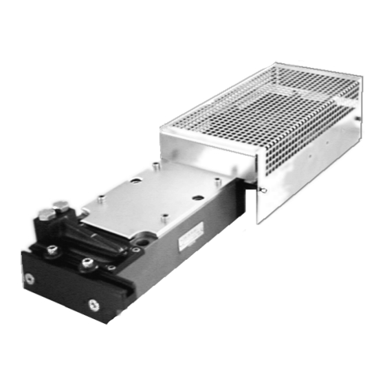
Bedienungsanleitung
Pneumatisches
Taktvorschubgerät
Typ
BV-100-...
BV-200-...
Operating
instructions
Pneumatic feed unit
Type
BV-100-...
BV-200-...
D/GB 1
Advertisement


Need help?
Do you have a question about the BV-200 Series and is the answer not in the manual?
Questions and answers