Table of Contents
Advertisement
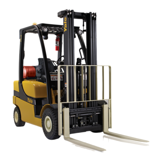
GLP20LX, GLP25LX, GDP20LX, GDP25LX (B974)
SECTION
FRAME............................................................................................................................
YANMAR DIESEL ENGINES..........................................................................................
PSI 2.4L ENGINE............................................................................................................
Cooling System........................................................................................................
FUEL SYSTEM PSI 2.4L................................................................................................
SINGLE SPEED PS CHAIN DRIVE PTO........................................................................
DRIVE AXLE AND DIFFERENTIAL ASSEMBLY REPAIR............................................
STEERING AXLE REPAIR.............................................................................................
BRAKE SYSTEM............................................................................................................
HYDRAULIC CLEANLINESS PROCEDURES...............................................................
HYDRAULIC GEAR PUMPS..........................................................................................
MAIN CONTROL VALVE................................................................................................
CYLINDER REPAIR (MAST S/N A698 AND A699).......................................................
WIRE HARNESS REPAIR..............................................................................................
ELECTRICAL SYSTEM..................................................................................................
ENGINE ELECTRICAL SYSTEM, PSI 2.4L ENGINE.....................................................
MAST REPAIR (S/N A698 AND A699)...........................................................................
METRIC AND INCH (SAE) FASTENERS.......................................................................
PERIODIC MAINTENANCE............................................................................................
CAPACITIES AND SPECIFICATIONS...........................................................................
DIAGRAMS AND SCHEMATICS....................................................................................
DIAGNOSTIC TROUBLESHOOTING MANUAL............................................................
SERVICE MANUAL CONTENTS
PART NO. 550109188 (12/14)
PART
YRM
NUMBER
NUMBER
550109110
0100 YRM 1766
524240453
0600 YRM 1205
550108890
0600 YRM 1755
550109111
0700 YRM 1767
550108892
0900 YRM 1757
550108495
1300 YRM 1740
550109112
1400 YRM 1768
550109113
1600 YRM 1769
550108498
1800 YRM 1743
550073240
1900 YRM 1620
550108499
1900 YRM 1744
550108500
2000 YRM 1745
550109114
2100 YRM 1770
524223769
2200 YRM 1128
550109115
2200 YRM 1771
550109116
2200 YRM 1772
550109117
4000 YRM 1773
524150797
8000 YRM 0231
550109197
8000 YRM 1774
550109119
8000 YRM 1775
550109120
8000 YRM 1776
550022929
9000 YRM 1434
REV
DATE
12/14
12/14
12/14
12/14
12/14
12/14
12/14
12/14
12/14
12/14
12/14
12/14
12/14
12/14
12/14
12/14
12/14
10/13
12/14
12/14
12/14
12/14
Advertisement
Table of Contents


Need help?
Do you have a question about the GLP20LX and is the answer not in the manual?
Questions and answers