Advertisement

SECTION
FRAME............................................................................................................................
OPERATOR'S CAB........................................................................................................
AC MOTOR REPAIR......................................................................................................
TRANSAXLE...................................................................................................................
STEERING SYSTEM......................................................................................................
BRAKE SYSTEM............................................................................................................
HYDRAULIC SYSTEM....................................................................................................
HYDRAULIC CLEANLINESS PROCEDURES...............................................................
MAIN CONTROL VALVES.............................................................................................
CYLINDER REPAIR (MAST S/N A270-72, A551, A555, A559, A626, A627, A751-52,
B551, B555, B586-91, B749-54, C661-63, C665, D507-09, D515, D562-64, E509,
E564)..........................................................................................................................
WIRE HARNESS REPAIR..............................................................................................
USER INTERFACE SUPERVISOR.................................................................................
USER INTERFACE SERVICE TECHNICIAN.................................................................
ELECTRICAL SYSTEM..................................................................................................
INDUSTRIAL BATTERY.................................................................................................
MAST REPAIR (S/N A270, A271, A272)........................................................................
MAST REPAIR (S/N C661, C662, C663, C665).............................................................
METRIC AND INCH (SAE) FASTENERS.......................................................................
PERIODIC MAINTENANCE............................................................................................
CAPACITIES AND SPECIFICATIONS...........................................................................
DIAGRAMS.....................................................................................................................
DIAGNOSTIC TROUBLESHOOTING MANUAL............................................................
Service information for Cummins diesel engines can be ordered through the Hyster Literature Distribution Center.
ERP15-20VT (G807)
SERVICE MANUAL CONTENTS
PART NO. 524320408 (12/14)
PART
YRM
NUMBER
NUMBER
524295629
0100 YRM 1329
550025937
0100 YRM 1446
524327049
0620 YRM 1385
524295630
1300 YRM 1330
524295631
1600 YRM 1331
524295632
1800 YRM 1332
524295633
1900 YRM 1333
550073240
1900 YRM 1620
524319495
2000 YRM 1334
524319496
2100 YRM 1382
524223769
2200 YRM 1128
524319497
2200 YRM 1335
524319498
2200 YRM 1336
524320282
2200 YRM 1337
524158040
2240 YRM 0001
524327054
4000 YRM 1386
524333799
4000 YRM 1405
524150797
8000 YRM 0231
524320290
8000 YRM 1339
524306565
8000 YRM 1340
524319503
8000 YRM 1341
524319504
9000 YRM 1377
REV
DATE
09/14
09/14
09/14
09/12
09/14
12/10
09/14
12/14
09/14
03/14
12/14
09/14
09/14
09/14
09/14
02/14
05/14
10/13
09/14
09/14
09/14
10/14

Advertisement

Table of Contents
loading

Summary of Contents for Yale ERP15-20VT

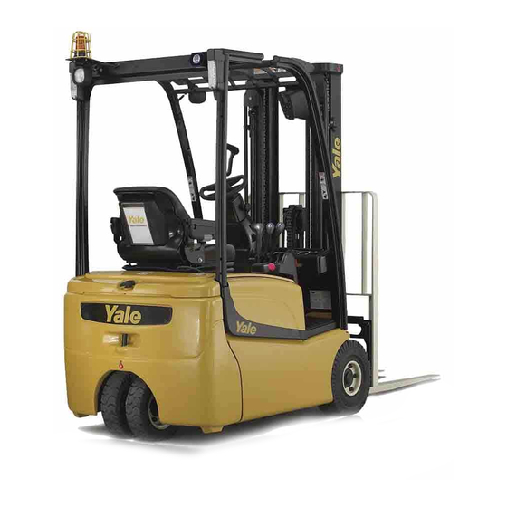
  • Page 1 ERP15-20VT (G807) SERVICE MANUAL CONTENTS PART SECTION NUMBER NUMBER DATE FRAME..........................524295629 0100 YRM 1329 09/14 OPERATOR'S CAB......................550025937 0100 YRM 1446 09/14 AC MOTOR REPAIR...................... 524327049 0620 YRM 1385 09/14 TRANSAXLE........................524295630 1300 YRM 1330 09/12 STEERING SYSTEM...................... 524295631...
  • Page 2 • Use the correct tools for the job. • Keep the tools clean and in good condition. • Always use YALE APPROVED parts when making repairs. Replacement parts must meet or exceed the specifications of the original equipment manufacturer. • Make sure all nuts, bolts, snap rings, and other fastening devices are removed before using force to remove parts.
  • Page 3: Table Of Contents

    During the Transaxle Warranty Period ......................After the Transaxle Warranty Period ......................Removing the Cover ..........................Installing the Cover ..........................Wet Brakes..............................This section is for the following models: ERP15-20VT (ERP030-040VT) [G807]; ERP16-20VF (ERP30-40VF) [A955] ©2012 Yale Materials Handling Corp.
  • Page 4: General

    Removing the cover from the housing will void the transaxle warranty. The transaxle warranty period may vary from truck hours or other warranties. Contact Yale Company Contact Management if you have questions about warranty status.
  • Page 5: Discharging The Capacitors

    Special tools are necessary to properly perform some Disconnect the battery and allow the capacitors to repairs. These tools are available from your Yale discharge before opening any compartment cov- dealer. Warranty will not cover damage resulting from ers or inspecting or repairing the electrical system.
  • Page 6: Transaxle Assembly

    Masts 4000 YRM 1405 for European and American 12. Position a floor jack under transaxle assembly. lift truck models Make sure assembly is properly balanced on floor • ERP15-20VT (ERP030-040VT) (G807) jack so it will not fall once mounting capscrews • ERP16-20VF (ERP30-40VF) (A955) have been removed.
  • Page 7: Remove The Parking Brake And Traction Motor

    Transaxle Assembly 1300 YRM 1330 REMOVE THE PARKING BRAKE AND WARNING TRACTION MOTOR The traction motor is heavy. Be sure that all lifting devices are suitable and of adequate capacity to lift WARNING the traction motor. Cleaning solvents can be flammable and toxic and 1.
  • Page 8: Install Transaxle To Frame

    1300 YRM 1330 Transaxle Assembly c. Lift traction motor and position it on transaxle c. Install four capscrews, lockwashers, and wash- using overhead lifting device. Guide traction ers to secure brake assembly. Tighten cap- motor shaft into transaxle through input seal. screws to 8 N•m (71 lbf in).
  • Page 9: Maintenance And Repair

    Masts 4000 YRM 1405 for European and American lift truck models 14. Connect battery connector, turn key switch to ON • ERP15-20VT (ERP030-040VT) (G807) position, and test lift truck for proper operation. • ERP16-20VF (ERP30-40VF) (A955) 15. Lower lift truck from the blocks.
  • Page 10 1300 YRM 1330 Maintenance and Repair 4. Position new cap over mast pin and onto transaxle. 5. Apply Loctite® 242 to threads and install four cap- screws and tighten alternately in small increments. Tighten capscrews to 24 N•m (216 lbf in). 6.
  • Page 11: Fluid Level Check

    2000 hours or one year. CAUTION Use only transmission fluid from approved ven- dors. Using fluid from unapproved vendors will void the warranty. Contact Yale Company Contact Management if you have questions about warranty status. Each transaxle has a separate fluid supply which must...
  • Page 12: Breather Repair

    See Periodic Maintenance 8000 YRM 1339 for lift 9. When fluid reaches bottom of check hole, install truck models check plug and fill plug and tighten each to 22 N•m • ERP15-20VT (ERP030-040VT) (G807) (192 lbf in). See Periodic Maintenance 8000 YRM 1373 for lift BREATHER REPAIR truck models •...
  • Page 13: Stud Repair

    See Periodic Maintenance 8000 YRM 1339 for lift truck models • ERP15-20VT (ERP030-040VT) (G807) See Periodic Maintenance 8000 YRM 1373 for lift truck models • ERP16-20VF (ERP30-40VF) (A955) 2.
  • Page 14: Brake Cylinder Repair

    1300 YRM 1330 Maintenance and Repair The service brake pedal in the operator compartment actuates the master cylinder sending pressurized fluid to the brake pistons in the transaxles through the ser- vice brake lines. 1. Remove transaxle from lift truck. Remove parking brake and traction motor from transaxle.
  • Page 15 Maintenance and Repair 1300 YRM 1330 1. SNAP RING 4. PISTON Figure 15. Removing the Cap 2. CAP 5. SEAL 3. O-RING 6. SPRING 5. Using a grind stone, slightly bevel the end of a 7/16 x 2 inch roll pin. Allow pin to cool. Figure 16.
  • Page 16: Input Seal Repair

    5. Clean around flange to remove any dirt or debris. CAUTION The transaxle is heavy and can be difficult to stabi- 6. Install input seal using Yale input seal installation lize when positioned with the studs down. Securely tool (refer to section General, Special Tools).
  • Page 17: After The Transaxle Warranty Period

    3. Install brake and traction motor on transaxle. Install transaxle on lift truck. See section Install Transaxle to Frame. 4. If the leak persists, the unit must be reported to Yale Company Contact Management. 1. SOCKET-HEAD SCREW After the Transaxle Warranty Period 2.
  • Page 18: Installing The Cover

    1300 YRM 1330 Maintenance and Repair Installing the Cover ensure that internal components seat properly and do not bind. Make sure assembly holes and dowels are aligned as the cover and housing meet. Lightly WARNING tap evenly around cover with a rubber mallet to seat Cleaning solvents can be flammable and toxic and cover onto housing.
  • Page 19: Wet Brakes

    The transaxle warranty period may vary from truck 9. Install a brake disc (internal spline) against brake disc (external spline) with rounded off side of teeth hours or other warranties. Contact Yale Company pointing upward. Contact Management if you have questions about warranty status.
  • Page 20 1300 YRM 1330 Maintenance and Repair b. Fill transaxle until fluid begins to emerge from CAUTION check hole. Make certain to use the proper magnetic plug for the c. Install check and fill plugs with new sealing drain plug. The drain plug is not interchangeable rings and tighten to 22 N•m (192 lbf in).
  • Page 21 NOTES ____________________________________________________________ ____________________________________________________________ ____________________________________________________________ ____________________________________________________________ ____________________________________________________________ ____________________________________________________________ ____________________________________________________________ ____________________________________________________________ ____________________________________________________________ ____________________________________________________________ ____________________________________________________________ ____________________________________________________________ ____________________________________________________________ ____________________________________________________________ ____________________________________________________________ ____________________________________________________________ ____________________________________________________________ ____________________________________________________________ ____________________________________________________________ ____________________________________________________________...
  • Page 22 Brake Pedal Assembly Repair 1800 YRM 1332 DISCHARGING THE CAPACITORS personal injury, discharge the capacitors before inspecting or repairing any component in the drive unit compartment. Make certain that the battery WARNING has been disconnected. DO NOT make repairs or adjustments unless you have been properly trained and authorized to do so.
  • Page 23 1800 YRM 1332 Brake Pedal Assembly Repair c. Remove nut, then slide bolt from assembly. See Figure 3 and Figure 4. d. Lift pedal from assembly. Recover washer and sleeve from pedal. See Figure 5. e. Remove bushings from pedal if necessary. 1.
  • Page 24 Brake Pedal Assembly Repair 1800 YRM 1332 ASSEMBLE b. Loosen locknuts and adjust capscrew so pedal is within the proper distance from the bracket. For the following procedures, see Figure 4, and Fig- ure 5. c. Retighten locknuts to secure capscrew in place. 1.
  • Page 25 1800 YRM 1332 Master Cylinder Repair Master Cylinder Repair REMOVE WARNING Always wear the proper protective equipment in- cluding eye protection and petroleum-resistant gloves when handling Dexron III. Thoroughly wash exposed areas of skin as soon as possible. CAUTION Protect the brake system from dirt and contami- nants during servicing procedures.
  • Page 26 Master Cylinder Repair 1800 YRM 1332 1. CYLINDER HOUSING 8. SPRING 15. WASHER 2. PISTON ASSEMBLY 9. RETAINING RING 16. COTTER PIN 3. CUP 10. BOOT 17. CLAMP 4. PISTON 11. PUSH ROD 18. RESERVOIR 5. SPACER 12. NUT 19. GASKET 6.
  • Page 27 1800 YRM 1332 Master Cylinder Repair 6. Loosen the nut and remove the clevis and nut from 8. Install master cylinder assembly to the truck. See the push rod if necessary. Install. 7. Remove the retaining ring and extract the piston INSTALL assembly from the cylinder housing.
  • Page 28 Master Cylinder Repair 1800 YRM 1332 To bleed air from the brake system: NOTE: Do not allow the boot to be twisted while adjust- ing the push rod length. 1. Remove the floor plates and check that the master cylinder reservoir is full of oil. 3.
  • Page 29 1800 YRM 1332 Brake Lines Brake Lines 4. Bleed the brake lines. Refer to Bleed the Brake WARNING System in this section. Always wear the proper protective equipment in- cluding eye protection and petroleum-resistant gloves when handling oil. Thoroughly wash oil from exposed areas of skin as soon as possible.
  • Page 30 Parking Brake 1800 YRM 1332 Parking Brake The parking brake consists of two identical spring-ap- plied, electrically-released brakes mounted directly to the drive motors. The controller breaks the power sup- ply to the brake coils, engaging the parking brake when the truck is stopped.
  • Page 31 (A955) or Periodic Maintenance 8000 YRM 1339 40VF) (A955) or Periodic Maintenance 8000 YRM for lift truck models ERP15-20VT (ERP030-040VT) 1339 for lift truck models ERP15-20VT (ERP030- (G807) for instructions on properly removing safety 040VT) (G807) for instructions on properly safety chains from the mast.
  • Page 32 Thank you very much for your reading. Please Click Here Then More Information.

This manual is also suitable for:

G807

Table of Contents