Code Reader CR8000 Integration Manual
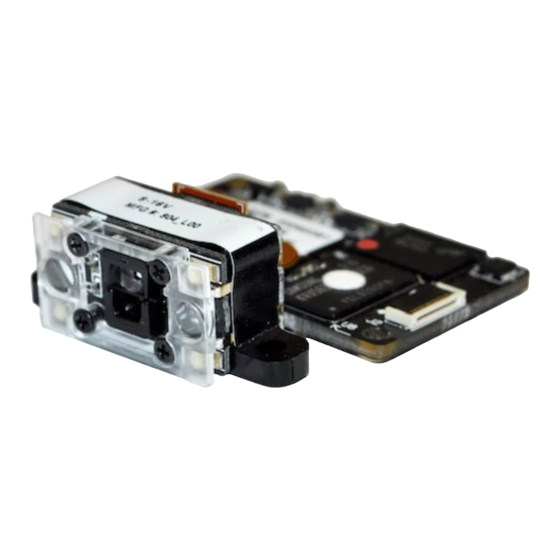
Decoded scan engine
Hide thumbs
Also See for Code Reader CR8000:
- Configuration manual (13 pages) ,
- Configuration manual (106 pages)
Table of Contents
Advertisement
Quick Links
Download this manual
See also:
Configuration Manual
Advertisement
Table of Contents

Subscribe to Our Youtube Channel
Related Manuals for Code Code Reader CR8000


Summary of Contents for Code Code Reader CR8000
- Page 1 INTEGRATION GUIDE CR8000 Decoded Scan Engine INTEGRATION GUIDE VERSION: 10 RELEASE DATE: MARCH 2017 www.codecorp.com Configuration Guide YouTube.com/codecorporation...
- Page 2 NO WARRANTY. This technical documentation is provided AS-IS. Further, the documentation does not represent a commitment on the part of Code Corporation. Code Corporation does not warrant that it is accurate, complete or error free. Any use of the technical documentation is at the risk of the user.
-
Page 3: Table Of Contents
Table of Contents 1 – CR8000 Introduction ..............4 5 – Configuration ................22 1.1 – Product Overview ............4 5.1 – Serial Commands ............22 1.2 – SKU Descriptions ............4 6 – Shipping Specifications ...............23 2 – Mechanical Specifications ............5 7 – General Specifications ..............24 2.1 –... -
Page 4: Cr8000 Introduction
Lottery, Age Verification, Direct Part Marking, Point of Sale, Self-Service based barcode readers. Code has overcome this challenge with a patented Kiosks and more. process that significantly reduces the reflections, thus making the barcodes easily identifiable. -
Page 5: Mechanical Specifications
2 - Mechanical Specifications The CR8000 is offered in multiple mechanical configurations. It can be ordered as either an assembly or unassembled with or without Scan Engine mounting tabs. 2.1 – Decoded Scan Engine Components Fully Assembled Unit CR8000 Decoded Scan Engine Individual Components Scan Engine (shown with tabs) Decode Board... -
Page 6: Scan Engine Components
2.3 – Scan Engine Components Blue LED Targeting Lens Red LED Illumination Lens High Density Field Lens Wide Field Lens Self-Tapping Screw Holes Printed Circuit Boards Connector, Receptacle, 30 pin, 0.4 mm pitch 2.4 – Scan Engine with Mounting Tabs Components Blue LED Targeting Lens Red LED Illumination Lens High Density Field Lens... -
Page 7: Scan Engine With Mounting Tabs Mechanical Specifications
13.53 does not require a washer, however, if one 9.16 [.532] 2.04 [.361] is desired, Code recommends a flat washer, [.080] No. 2 Screw Size, .19" OD, CLEARANCE HOLE FOR .01"-.03" thick. TOP VIEW #2 OR M2 SCREW (2 PLACES) For the Blind Holes, please use M2.2 x 4.5... -
Page 8: Cr8000 Decoded Scan Engine With Bracket Specifications
2.7 – Decode PCB Mechanical Specifications (continued) CR8013 2.54 [.100] HIROSE DF40C-10DS-0.4V(51) CLEARANCE HOLE MICRO USB TYPE B 2PLACES TP 31 PIN 1 TP 32 PIN 10 22.75 25.00 [.896] [.984] 2.25 [.089] PIN 1 PIN 30 34.50 5.65 [.222] 39.00 [1.358] 2.25... -
Page 9: Enclosure Specifications
2.8 – CR8000 Decoded Scan Engine with Bracket Specifications (continued) Non-Threaded Mounting Holes There are two 2.50 mm diameter non-threaded 3.24 3.24 mounting holes on the CR8000 bracket, 2X 2.50 [.098] 2X 2.50 [.098] [.128] [.128] shown below. ± .07 THRU ±... -
Page 10: Optical Considerations
If your design constraints prevent the window from being mounted within necessary to install a window in front of the optics of the Scan Engine. 0.5 mm of the face of the engine, Code recommends an anti-reflective Although many different types of materials can be considered, Code makes (AR) coating be applied to both window surfaces (front and back). -
Page 11: Imager Field Of View
3.2 – Imager Field of View The CR8000 Decoded Scan Engine contains an imager with both Wide Angle and High Density Fields. The Field of View for both Wide Angle and High Density optics is shown below for Horizontal and Vertical positioning of the imager: CR8000 Field of View Diagram HIGH DENSITY FOV... -
Page 12: Electrical Specifications
4 - Electrical Specifications 4.1 – System Requirements Power Supply: The CR8000 is powered from the host via the V and Gnd Power Sequencing: There is no special power sequence needed for the pins. V must be within the range specified in Section 4.15 when measured CR8000 as long as the max and min voltage and current specifications are at the decoding board. -
Page 13: Host Interface Pinouts (Cr8012 Rs232)
4.3 – Host Interface Pinouts (CR8012 RS232) Name Type Description Note RS232 Polarity Input RS232 polarity control. When high, all RS232 signals have their normal polarity. When low, all RS232 signals have inverted polarity. Power Power supply voltage input Power Power supply and signal ground Input RS232 receive data, TTL level... -
Page 14: Electrical Control Signals (Cr8011 And Cr8012 Only)
Interface Configuration Document (ICD), available on order for nWakeUp to awaken the CR8000 on assertion. Also note that when the Code website (www.codecorp.com). the sleep state is not being used, this pin should be left open, not tied low. -
Page 15: Power On (Boot) Timing Diagram (Cr8011 And Cr8012 Only)
4.8 – Power On (Boot) Timing Diagram (CR8011 and CR8012 only) The PwrDwn signal will transistion to HIGH shortly after V is applied and will remain HIGH until the main application starts. nBeeper nGoodRead PwrDwn TPU1 TPU3 TPU2 Parameter Symbol Typical Unit Note... -
Page 16: Power Down Timing Diagram
4.9 – Power Down Timing Diagram Power (V ) can be removed at any time except when the unit is performing an upgrade. Removing power during an upgrade may cause the unit to become unusable. Outputs TPD1 Outputs: PwrDwn, nGoodRead, nBeeper Parameter Symbol Typical... -
Page 17: Image Capture And Decode Timing Diagram
(2C). To get more information on register functions, refer to the Interface selected, the confirmation time register (0xE3), and where the imager is in Configuration Document (ICD), available on the Code website (www. the capture cycle. The time to decode an image can depend on the image codecorp.com). -
Page 18: Ribbon Cable Diagram (Decode Board To Host Interface On Cr8011 And Cr8012)
4.12 – Flex Cable Diagram (Imager Board to Decoder Board on All Models) (continued) 29.00 [1.141] 9.00 [.354] 7.57 [.298] 17.57 [.691] 9.00 52.30 [.354] [2.050] 19.00 9.00 [.748] [.354] 17.90 [.704] Reverse Flex 5.00 [.196] 9.00 [.354] In-line (Centerline) Flex UNITS = MM [INCHES] 4.13 –... -
Page 19: Electrical Characteristics (Dc) - Absolute Ratings (Min And Max)
4.14 – Electrical Characteristics (DC) – Absolute Ratings (Min and Max) Parameter Symbol Unit Note DC Supply Voltage -0.5 DC Input Voltage -0.5 DC Output Voltage -0.5 Output source or sink current 4.15 – Electrical Characteristics (DC) – Operating Conditions Parameter Symbol Typical... -
Page 20: Decode Pcb To Scan Engine Pcb Connector
4.16 – Decode PCB to Scan Engine PCB Connector Name Type Description Note Power power to Optical Engine Power power to Optical Engine 1.8V Power 1.8V power to Optical Engine 1.8V Power 1.8V power to Optical Engine Power Power and signal ground ExtClk Output External clock to imager... -
Page 21: Decode Pcb Expanded Illumination Connector
4.17 – Decode PCB Expanded Illumination Connector The board connector is a Hirose DF40C-10DS-0.4V(51) and mates to a cable containing a Hirose DF40C-10DP-0.4V(51) connector. Name Type Description Note Power Power supply voltage input Power Power supply voltage input Illumination IO 0 Bidirectional Illumination Communications Line, UART Port4 TX TTL Level, I2C SDA... -
Page 22: Configuration
The details are documented in the Interface are disabled by default. Text commands can be enabled by sending Configuration Document (ICD), which is available on the Code the following sequence: website (www.codecorp.com). -
Page 23: Shipping Specifications
6 – Shipping Specifications The CR8000 engines are shipped in bulk packaging in a 10-unit box. Each unit is individually packaged in an ESD safe bag and separated by cardboard dividers. The Flex Cables are packaged in an ESD safe bag and 10124512 10045123 20014541... -
Page 24: General Specifications
Humidity 5% to 95% non-condensing 1D Barcodes Codabar, Code 11, Code 32, Code 39, Code 93, Code 128, Interleaved 2 of 5, GS1 DataBar (RSS), Hong Kong 2 of 5, Maxtrix 2 of 5, MSI Plessey, Pharmacode, Plessey, Straight 2 of 5, Telepen, Trioptic, UPC/EAN/JAN Stacked 1D Barcodes PDF417, Micro PDF417, Codablock A &... -
Page 25: Reading Range Specifications
Wide Area Field and the High Density Field enabled and active for decoding. Test Barcode Min Inches (mm) Max Inches (mm) 3 Mil Code 39 3.1" (80 mm) 4.0" (102 mm) 7.5 Mil Code 39 1.3" (33 mm) 7.2"... -
Page 26: Warranty
Code Corporation at: ii) replace the Code product with a product that is new or refurbished product with equivalent functionality and performance, which may include replacing a product CodeOne Service Center that is no longer available with a newer model product;... -
Page 27: Appendix A: Development Kit User Guide
10 – APPENDIX A: Development Kit User Guide CR8000 POLARITY D– LED0 WAKE UP LED1 LED0 BEEPER TRIGGER LED1 WAKE UP TRIGGER EXPANDED ILLUMINATION TRIGGER POLARITY BOOT SELECT 10.1 – CR8000 Development Board Development Kit Overview Scan Interface The CR8000 development kit includes everything needed to integrate J1 interfaces to a RJ-50 connector that carries both USB and RS-232 the CR8000 (specifically the CR8011 or CR8012) Scan Engine into a signals to an external interface. -
Page 28: Development Board Connections
10.2 – Development Board Connections CR8000 Connections CR8000 The CR8000 connects to the development board via J23 and J24. POLARITY D– LED0 WAKE UP LED1 LED0 BEEPER TRIGGER LED1 TRIGGER WAKE UP EXPANDED ILLUMINATION TRIGGER POLARITY BOOT SELECT RJ50 System Header CR8000 The majority of system communication goes through the RJ50 System Header. -
Page 29: Development Board Jumpers
10.2 – Development Board Connections (continued) Illumination Expansion Header The CR8000 provides extra I/O for control of CR8000 third party illumination boards. The Illumination Expansion Header (J19) allows user POLARITY development of these boards from a simple D– low-density connector. The following table defines LED0 the pin-out of J19: WAKE UP... -
Page 30: Development Board Fuses
10.3 – Development Board Jumpers (continued) Serial Polarity and Boot Select Jumpers CR8000 J5 selects whether or not the primary RS-232 data are inverted, and the combination of J6 and POLARITY SW2 will select the boot mode the kit comes up D–... - Page 31 Illumination header, J19, the fuse that protects the circuit is F1, which is located on the front side of the board, next to J19. Both fuses have the same part number: • Code P/N: V005953 • Description: Fuse, 0.75 Amp 0603 • Manufacturer: Littelfuse •...
-
Page 32: Appendix B: Optimizing For Low Power Applications
11 – APPENDIX B: Optimizing for Low Power Applications Achieving low power consumption with the CR8000 requires that certain mode. This appendix describes these operations. This applies to the setup and configuration values be programmed into the Scan Engine, as RS232 interface model only. -
Page 33: Timing Specifications
11.2 – Communications from Sleep Mode (continued) Rapid Scanning and Returning to Sleep The following diagram shows the timing diagram nWakeUp for scanning a barcode when the unit is in sleep mode. When register 0x9F is minimized, the unit WUPW PwrDwn will consume the minimum amount of power possible.
Need help?
Do you have a question about the Code Reader CR8000 and is the answer not in the manual?
Questions and answers