Table of Contents
Advertisement
Available languages
Available languages
Quick Links
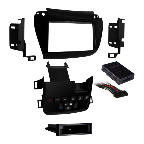
KIT COMPONENTS
• A) Radio trim panel • B) Radio brackets • C) A/C button housing • D) Pocket • E) Console bracket • F) (6) #8 x 3/8" Phillips pan-head screws
• G) (2) Panel clips • H) Climate extension harness (not shown) • I) Axxess interface and harness (not shown)
A
B
The World's best kits.
®
Dodge Journey 2011-up*
*Visit MetraOnline.com for up-to-date vehicle specific applications.
KIT FEATURES
• ISO DIN radio provision with pocket
• ISO DDIN radio provision
• Included interface retains factory screen
• Painted matte black to match factory finish
Note: Does not retain sound from "Driver Convenience Group"
C
D
F
MetraOnline.com
E
G
© COPYRIGHT 2018 METRA ELECTRONICS CORPORATION
99-6520B
I N S TA L L AT I O N I N S T R U C T I O N S
U.S. Patent # D755,778 D768,126
TABLE OF CONTENTS
Dash Disassembly . ..............................................2-3
Kit Preparation . ......................................................4
Kit Assembly
– ISO DIN radio provision with pocket . ................5
– ISO DDIN radio provision . ...................................5
Axxess interface installation . ............................6-11
WIRING & ANTENNA CONNECTIONS
Wiring Harness: Interface and harnesses included
Antenna Adapter: 40-EU10 (sold separately)
Steering Wheel Control Interface: ASWC-1
(sold separately)
TOOLS REQUIRED
• Panel removal tool • Phillips screwdriver
CAUTION!
All accessories, switches, climate
controls panels, and especially air bag indicator
lights must be connected before cycling the
ignition. Also, do not remove the factory radio
with the key in the on position, or while the
vehicle is running.
REV. 8/10/18 INST99-6502B
Advertisement
Table of Contents

Subscribe to Our Youtube Channel
Related Manuals for Metra Electronics 99-6520B


Summary of Contents for Metra Electronics 99-6520B
- Page 1 Also, do not remove the factory radio with the key in the on position, or while the vehicle is running. The World’s best kits. MetraOnline.com ® © COPYRIGHT 2018 METRA ELECTRONICS CORPORATION REV. 8/10/18 INST99-6502B...
- Page 2 DASH DISASSEMBLY 1. Unclip and remove the trim panel along the top of the glove box over to the passenger side a/c vent. (Figure A) 2. Unclip and remove the small trim panel to the left of the hazard button. (Figure A) 3. Remove (2) Phillips screws securing the climate/radio panel, then unclip, unplug and remove the panel. (Figure B) Note: A climate extension harness is provided to extend this harness lower (Figure A) (Figure B) in the center console where the climate will be relocated to. 4. Remove (4) Phillips screws securing the radio chassis. Slide the chassis out, then unplug and remove the chassis. (Figure C) Note: The white 4-pin harness will be reused in Kit Assembly. (Figure D) Continued on the next page (Figure C) (Figure D) 1.800.221.0932 MetraOnline.com...
- Page 3 DASH DISASSEMBLY (CONT) 5. Pull up on shift knob to remove. (Figure D). 6. Unclip and remove the shifter trim panel including the cup holders from the top of the center console. (Figure E) 7. Push down and then pull back and out on the pocket in the front of the console. Note: You may need to pull the console side panels outward at the same time as pulling out on pocket. (Figure F) (Figure D) (Figure E) (Figure F) 8. Remove the (2) metal panel clips on the front side of the pocket and save for Kit Preparation.
-
Page 4: Kit Assembly
KIT PREPARATION 1. Attach the console bracket to the back of the A/C button housing using (4) of the provided #8 x 3/8” Phillips screws. (Figure A) 2. Install the (2) metal panel clips saved from the pocket disassembly onto the console bracket. (Figure A) 3. Using the climate extension harness provided, connect the A/C button housing assembly to the factory wiring harness in the vehicle. 4. Secure the A/C button housing into the pocket space in the front of the center console. (Figure B) (Figure A) (Figure B) Continue to Kit Assembly 1.800.221.0932 MetraOnline.com... -
Page 5: Iso Din Radio Provision With Pocket
KIT ASSEMBLY ISO DIN radio provision with pocket ISO DDIN radio provision 1. Secure the radio brackets to the pocket 1. Break the small locating pin from the using the (2) #8 x 3/8” Phillips screws inside surface of each bracket. provided. (Figure A) (Figure A) Note: Pins on brackets will align with 2. Secure the radio brackets to the radio front mounting hole of pocket. using the screws supplied with the radio. (Figure A) 2. Remove the metal DIN sleeve and trim Remove pin ring from the aftermarket radio. Continue to Axxess Interface Installation 3. Slide the radio into the bracket/pocket assembly, then secure it to the assembly (Figure A) (Figure A) -
Page 6: Table Of Contents
AXXESS INTERFACE INSTALLATION INTERFACE FEATURES TABLE OF CONTENTS • Provides accessory power (12-volt 10-amp) Connections .............................. 7 • Retains R.A.P. (retained accessory power) Installation ...............................8 • Used in amplified and non-amplified systems Programming ............................8 • Provides NAV outputs (parking brake, reverse, V.S.S.) Final assembly ............................8 • Prewired ASWC-1 harness (ASWC-1 sold separately) Audio level adjustment ...........................8 • Retains balance and fade Screen operation ............................9 • Ability to add an aftermarket backup camera or additional video input Video option screen ..........................10 • Retains the factory display screen Updating . -
Page 7: Connections
CONNECTIONS From the 16-pin harness with stripped leads to the aftermarket radio: From the 6520 harness to the aftermarket radio: • Connect the Black wire to the ground wire. • Connect the Red wire to the accessory wire. • Connect the Yellow wire to the battery wire. Note: If also installing an ASWC-1 (sold separately), there will be a Red wire on the 6520 harness to connect as well. • Connect the Gray wire to the right front positive speaker output. • Connect the Orange/White wire to the illumination wire, if applicable. • Connect the Gray/Black wire to the right front negative speaker output. • Connect the White wire to the left front positive speaker output. • If the vehicles equipped with a factory amplifier, connect the Blue/White wire to the amp turn-on wire. • Connect the White/Black wire to the left front negative speaker output. • Connect the Green wire to the left rear positive speaker output. -
Page 8: Installation
Attention! For models with a 8-inch screen, update the interface via the Axxess Updater available 1. Secure the completed assembly to the dash using the factory hardware. at axxessinterfaces.com. Select “8-inch screen” once prompted to. Instructions to update the 2. Attach the (2) panel clips provided to the 99-6520B radio trim panel, then reassemble the interface are available at the end of this instruction booklet. dash in reverse order of disassembly using the 99-6520B panel. -
Page 9: Screen Operation
SCREEN OPERATION 1. Radio button – Show the current time 2. Player button – Not used in this application 3. Climate button – Takes you to the climate screen 4. Setting button – Takes you to the setting screen 5. More button – Shows the outside temperature and current time 6. Screen Off – Turns the display off REV. 8/10/2018 INST99-6520B... -
Page 10: Video Option Screen
VIDEO OPTION SCREEN Once in the setting screen, scroll down 3. After you have made your selection, tap to the Customize button. Pressing the the “Done” button located on the upper button will take you to the video option left hand corner of the screen to exit. screen. (Figure A) The About button will display the From here select Video 2, then select an current software of the kit, and also the option for the video input: AUX Video, VIN of the vehicle. Backup Camera, Not Used. (Figure B) Note: The Backup camera input is controlled by data and will activate when you put the (Figure A) (Figure C) vehicle in reverse. Note: AUX video is controlled by data and will only work while the vehicle is in park. -
Page 11: Updating
UPDATING Attention: In order to update the interface, the interface must have power from the vehicle. • Download and install the Axxess Updater from axxessinterfaces.com. • Connect the USB-MINI-CAB update cable (sold separately) between the interface and the computer. The cable will connect into the Micro-B USB port inside the interface. • Remove the main connector from the vehicle. This will remove power from the interface. • Reconnect the main harness back to the vehicle, putting power back to the interface. • From the Start Menu of the computer, click on “Axxess Updater”, and then click “Update Firmware”. The interface will begin to update at this point. Note 1: If 30 seconds elapses after powering the interface, you will need to remove power from the interface, reapply power, then start the update process again. Note 2: Please note which firmware downloaded to the interface. This will help in troubleshooting, if need be. REV. 8/10/2018 INST99-6520B... - Page 12 Log onto www.installerinstitute.com or call 800-354-6782 for more information and take steps toward a better tomorrow. Metra recommends MECP certified technicians The World’s best kits. MetraOnline.com ® © COPYRIGHT 2018 METRA ELECTRONICS CORPORATION REV. 8/10/18 INST99-6502B...
- Page 13 Además, no quite el radio de fábrica con la llave en la posición o de encendido ni con el vehículo funcionando. The World’s best kits. MetraOnline.com ® © COPYRIGHT 2018 METRA ELECTRONICS CORPORATION REV. 8/10/18 INST99-6502B...
- Page 14 DESMONTAJE DEL TABLERO 1. Desenganche y quite el panel de la moldura a lo largo de la parte superior de la guantera sobre la rejilla de aire acondicionado del lado del pasajero. (Figura A) 2. Desenganche y quite el panel de moldura pequeño a la izquierda del botón de las luces intermitentes.
- Page 15 DESMONTAJE DEL TABLERO (CONT) 5. Jale hacia arriba la perilla de la palanca de velocidades para quitarla. (Figura D) 6. Desenganche y quite el panel de la moldura de la palanca de velocidades, incluyendo los portavasos de la parte superior de la consola central. (Figura E) 7.
- Page 16 PREPARACIÓN DEL KIT 1. Una el soporte de la consola a la parte posterior de la carcasa del botón de aire acondicionado con (4) de los tornillos Phillips #8 x 3/8” proporcionados. (Figura A) 2. Instale los (2) ganchos metálicos del panel que guardó...
- Page 17 ENSAMBLE DEL KIT ISO DIN radio provision with pocket ISO DDIN radio provision 1. Atornille los soportes del radio al 1. Quiebre el pequeño pin que está en la cavidad con los (2) tornillos Phillips #8 superficie interior de cada soporte. de 3/8”...
- Page 18 INSTALACIÓN DE LA INTERFASE AXXESS CARACTERÍSTICAS DE LA INTERFASE INDICE • Provee corriente de accesorios (12 voltios 10 amperes) Conexiones ............................... 7 • Retiene R.A.P. (corriente de accesorio retenida) Instalación ..............................8 • Se usa en sistemas amplificados y no amplificados Programación ............................8 •...
- Page 19 CONEXIONES Del arnés de 16 pins con conectores pelados al radio de mercado secundario: Desde el arnés 6520 al radio de mercado secundario: • Conecte el cable negro al cable de tierra. • Conecte el cable rojo al cable de accesorios. •...
- Page 20 Axxess disponible en axxessinterfaces.com. Seleccione “pantalla de 8 pulgadas” 2. Conecte los (2) clips del panel provistos al panel de moldura de radio 99-6520B, luego una vez que se le solicite. Las instrucciones para actualizar la interfaz están disponibles al final de vuelva a armar el tablero en el orden inverso al de desmontaje usando el panel 99-6520B.
- Page 21 OPERACIÓN DE LA PANTALLA 1. Botón de radio – Muestra la hora actual 2. Botón de reproducción – no se utilizará en esta aplicación. 3. Botón de clima – Lo lleva a la pantalla de clima 4. Botón de configuración – Lo lleva a la pantalla de configuración 5.
- Page 22 PANTALLA DE OPCIÓN DE VIDEO Una vez en la pantalla de configuración, 3. Después de hacer su selección, toque desplácese hacia abajo hasta el botón el botón “Listo” ubicado en la esquina Personalizar. Al presionar el botón, superior izquierda de la pantalla para salir. accederá...
- Page 23 ACTUALIZANDO Atención: Para actualizar la interfaz, la interfaz debe tener energía del vehículo. • Descargue e instale Axxess Updater de axxessinterfaces.com. • Conecte el cable de actualización USB-MINI-CAB (se vende por separado) entre la interfaz y la computadora. El cable se conectará al puerto USB Micro-B dentro de la interfaz. •...
- Page 24 800-354-6782 para obtener más información y avance hacia un futuro mejor. Metra recomienda técnicos con certificación del Programa de Certificación en Electrónica Móvil (Mobile Electronics Certification Program, MECP). The World’s best kits. MetraOnline.com ® © COPYRIGHT 2018 METRA ELECTRONICS CORPORATION REV. 8/10/18 INST99-6502B...
Need help?
Do you have a question about the 99-6520B and is the answer not in the manual?
Questions and answers