
Related Manuals for Impresind Cold Air FPA109


Summary of Contents for Impresind Cold Air FPA109
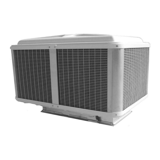
- Page 1 RAFFRESCATORI EVAPORATIVI ADIABATICI ADIABATIC EVAPORATIVE COOLERS ISTRUZIONI PER L’INSTALLAZIONE INSTALLATION INSTRUCTIONS ISTR-INST-CA18 Ed.01-2018...
-
Page 2: Table Of Contents
INDICE INFORMAZIONI GENERALI ..........................3 Premessa ................................ 3 SEZIONE 1 – CARATTERISTICHE ........................4 1.1 Presentazione del Raffrescatore Evaporativo ColdAir ................4 1.2 Uso previsto .............................. 4 1.3 Dati identificativi della macchina ....................... 5 1.4 Quadri elettrici ............................5 SEZIONE 2 – TRASPORTO, MOVIMENTAZIONE, DISIMBALLAGGIO, IMMAGAZZINAMENTO ....5 2.1 Ricevimento materiale .......................... -
Page 3: Informazioni Generali
In caso di smarrimento o danneggiamento del presente manuale, richiederne immediatamente una copia contattando il Servizio Assistenza Tecnica della Impresind Srl, citando i dati identificativi dell’impianto riportati sulle targhe dati. La macchina è conforme alle seguenti direttive comunitarie: ... -
Page 4: Sezione 1 - Caratteristiche
E’ assolutamente vietato modificare la macchina e la sua destinazione d’uso La Impresind Srl declina ogni responsabilità per eventuali danni che potrebbero, direttamente o indirettamente, derivare da persone esposte o cose, in conseguenza di uso improprio da quello per cui è... -
Page 5: Dati Identificativi Della Macchina
In caso di richiesta di Assistenza Tecnica o di parti di ricambio, citare sempre il modello ed il numero di matricola della macchina. 1.4 Quadri elettrici I quadri elettrici , eventualmente forniti dalla Impresind s.r.l. sono realizzati in conformità alla norma EN 60204/1:2016 E’ assolutamente vietato modificare i quadri elettrici SEZIONE 2 –... -
Page 6: Sollevamento Con Funi
2.2.2 Sollevamento con funi E’ vivamente consigliato applicare le funi come indicato in figura, interponendo distanziali di lunghez- za adeguata per impedire che le funi stringendosi non danneggino l’involucro. Dato il notevole peso, i modelli della serie TC ed i modelli in versione “SD” sono stati dotati di fori passanti opportunamente posizionati per l’introduzione di tubi che consentono il sollevamento con funi anche quando privi di imballo. -
Page 7: Sezione 3 - Posizionamento E Installazione
SEZIONE 3 – POSIZIONAMENTO E INSTALLAZIONE 3.1 Avvertenze generali Prima di procedere all’installazione assicurarsi che ogni raffrescatore evaporativo sia stato disimbal- lato e ne sia stata verificata l’integrità di tutti i suoi componenti. La messa in opera e l’installazione dei raffrescatori evaporativi sono operazioni che possono compro- mettere il buon funzionamento dell’impianto o, peggio, causare danni irreversibili alla macchina. -
Page 8: Raffrescatori Evaporativi Serie Tc
Collegare al portagomma del distributore il tubo flessibile proveniente dal- la pompa e fissarlo me- diante fascetta stringitu- Inserire le griglie ai lati e al posteriore della macchina, fissandole con i fermagli forniti in dotazione. Non montare la griglia sul lato anteriore (lato componenti/ collegamenti). -
Page 9: Installazione A Parete/Finestra
3.3 Installazione a parete/finestra 3.3.1 Raffrescatori evaporativi serie TA Predisporre e fissare un telaio per il sostegno della macchina ed un canale flangiato di ingresso aria avente le medesime dimensioni flangia del tronco di canale della macchina. La macchina è provvista di un tronco di canale flangiato che andrà fis- sato sulla flangia del canale precedentemente predisposto. -
Page 10: Raffrescatori Evaporativi Serie Ta & Tc Versione "Sd
3.3.3 Raffrescatori evaporativi serie TA & TC versione “SD” Tutte le macchine in versione “SD” hanno un condotto di immissione aria orizzontale (il tronco posto alla base serve solo come struttura di sostegno e di appoggio) Predisporre e fissare un telaio per il sostegno della macchina ed un canale flangiato di ingresso aria avente le medesime dimensioni della boc- ca di mandata della macchina. -
Page 11: Raffrescatori Evaporativi Serie Fpa
3.3.4 Raffrescatori evaporativi serie FPA 3.3.4.1 Installazione a parete Fissare alla parete la staffa di sostegno, fornita in dotazione alla macchina, dopo aver predisposto il foro per il passaggio del ca- nale di mandata aria. Montare sul lato posteriore del raffrescattore evaporativo (lato ventilatore) il primo tratto del canale di mandata aria di sezione quadra 600x600. -
Page 12: Note A Completamento
3.4 Note a completamento Predisporre all’interno dell’edificio i punti d’ancoraggio per le catene di sostegno della condotta d’immissione aria. Questi dovranno essere definiti in modo tale che le catene non provochino ec- cessivi sforzi sulla condotta stessa. Accertarsi che questa sia in asse con la macchina Per l’ancoraggio al soffitto o a parete dei canali utilizzare catene e relativi accessori muniti di certifi- cato di collaudo, realizzati in acciaio zincato o inox, aventi il diametro del filo non inferiore a 3mm o comunque dimensionato in relazione al peso che dovrà... -
Page 13: Allacciamento Alla Rete Idrica
4.1 Dispositivi di protezione Per ottemperare alle disposizioni contenute nelle Direttive Comunitarie applicabili all’unità alla quale è riferito il presente manuale d’uso e manutenzione, Impresind Srl ha predisposto sull’unità stessa i si- stemi di sicurezza previsti dalla legislazione vigente. 4.2 Segnaletica applicata a bordo macchina... -
Page 14: Rischi Residui
4.4 Rischi residui Vietato utilizzare acqua per pulire componenti elettromeccanici. Pericolo di elettrocuzione Prestare attenzione al movimento del ventilatore. Non introdurre gli arti. Pericolo meccanico 4.5 Situazioni d’emergenza In caso di emergenza fermare immediatamente l’apparecchio e aprire il circuito elettrico tra- mite il sezionatore onnipolare, identificare ed eliminare il problema controllandone le cause di origine, contattare il servizio di assistenza tecnica. - Page 15 INDEX GENERAL INFORMATION ..........................3 Preamble ................................. 3 SECTION 1 – CHARACTERISTICS ........................4 1.1 Presentation of the ColdAir Evaporative Cooler ..................4 1.2 Foreseen use ............................4 1.3 Machine identification data ........................5 1.4 Electrical boards ............................5 SECTION 2 – TRANSPORTATION, HANDLING, UNPACKING, STORAGE ..........5 2.1 Delivery of the unit ............................
- Page 16 GENERAL INFORMATION PREAMBLE Dear Customer, We thank you for chosing an Impresind product and we would like to inform you that: • The contents of this document are for information purposes only and are subject to modifica tions without notice;...
- Page 17 It is absolutely forbidden to make modifications to the machine and its destination of use. Impresind Srl declines all responsibility for any damages which may be, directly or indirectly, caused to exposed persons or property, due to improper use or use of the machine for differ-...
-
Page 18: Schemi Di Collegament0 Elettrico
If Technical Assistance or spare parts are required, always supply the machine model and serial number. 1.4 Electrical boards Any electrical boards supplied by Impresind s.r.l. are manufactured according to EN 60204/1:2016 regulations. It is absolutely forbidden to make modifications to the electrical board. - Page 19 2.2.2 Lifting with cables We suggest to attach the cables as shown, inserting spacers of an adequate length to prevent the cables from damaging the casing when tightened. Because of the heavy weight, TC models and “SD” version, when unpacked, are provided with pun- ched brackets to allow to lift them by using appropriate metal tubes.
- Page 20 SECTION 3 – POSITIONING AND INSTALLATION 3.1 General warnings Before proceeding to install, make sure that each evaporative cooling unit has been unpacked and checked for damage (check any components). Positioning and installation of the evaporative cooling units must be carried out by qualified personnel and by observing the laws in force in the country of destination.
- Page 21 Connect the distributor hose-end fitting to the flexible hose coming from the pump and fix them with an hose clamp. Insert the grates on the sides and rear of the unit and fix them by using the clips provided. Do not assemble the front unit grate (connections/components side). At first insert the clips till to their first “click”...
- Page 22 3.3 Wall/window installation 3.3.1 TA evaporative coolers Prepare and fix an air inlet flanged duct and a frame to hold up the unit. The flange has to be of the same dimension of the unit’s trunk duct flan- The unit is equipped with a trunk of flanged duct that will be fixed to the flange of the inlet duct prepared before and with two side girders bars that will be fixed on the frame.
- Page 23 3.3.3 TA & TC evaporative coolers “SD” version The “SD” version machine have a orrizontal ait duct (and not vertical duct). The duct provide at the base of machine , it is not the air duct; but it is a structural working. Prepare and fix an air inlet flanged duct and a frame to hold up the unit.
- Page 24 3.3.4 FPA evaporative coolers 3.3.4.1 Wall installation When the hole in the wall for the passage of the air inlet duct is done, fix the supplied support bracket to the wall. Install the first section of air duct (area 600x600) on the rear of the unit (fan side).
- Page 25 3.4 Notes Inside the building, prepare the anchor points for the support chains of the air inlet duct. These must be placed in a position to avoid excessive stress to the air inlet duct and make sure they are on the same axis as the machine.
- Page 26 4.1 Protection devices To comply with the instructions of the European Community Directives, applicable to the unit referred to in this use and maintenance manual, Impresind Srl has designed the safety systems on the unit foreseen by the regulations in force 4.2 Caution signs applied on the unit...
- Page 27 4.5 Emergency situations In case of emergency immediately turn the machine off and cut off the electrical circuit through the omnipolar isolator switch, identify and solve the problem, contact Impresind af- ter-sales service. It is absolutely forbidden to use water to put out fires, use exclusively powder or CO2 extin- guishers.
- Page 28 FPA109 & FPA159 TA159...
- Page 29 TA209 TA309...
- Page 30 TC109 TC209...
- Page 31 TC109-SD TA209-2SD...
- Page 32 SCHEMA ELETTRICO—ELETTRICAL SKETCH...
-
Page 33: Caratteristiche Tecniche
CARATTERISTICHE TECNICHE TECHNICAL FEATURES Modello FPA109 FPA159 TA159 TA209 TA209-2SD TA309 Model Portata d’aria Air flow Velocità 10000 13000 13000 20000 20000 27000 Fan speed 7500 9700 9700 15000 15000 19000 5000 6500 6500 10000 10000 13500 Alimentazione Volt 230V/~50Hz 230V/~50Hz 230V/~50Hz 230V/~50Hz... - Page 34 CARATTERISTICHE TECNICHE TECHNICAL FEATURES Modello TC109 TC109SD TC209 Model Portata d’aria Air flow Velocità 10000 10000 20000 Fan speed 6500 6500 10000 Alimentazione Volt 400V/3N~50Hz 400V/3N~50Hz 400V/3N~50Hz Power supply Corrente assorbita Current Potenza elettrica Power consumption Consumo acqua* lt/h Water consumption* Ingresso acqua Ø...
- Page 35 Impresind Srl Via 1° Maggio 24, 20064 Gorgonzola (Milano, Italy) Tel. +39 02 95741932 Fax +39 02 95740637 e-mail impresind@impresind.it STP101.119 www.impresind.it...
Need help?
Do you have a question about the Cold Air FPA109 and is the answer not in the manual?
Questions and answers