RenewAire DN-Series Installation, Operation & Maintenance Manual
Doas indoor. for commercial
applications.
Hide thumbs
Also See for DN-Series:
- Installation, operation and maintenance manual (164 pages) ,
- Supplemental manual (60 pages) ,
- Instruction manual (36 pages)

Subscribe to Our Youtube Channel
Related Manuals for RenewAire DN-Series


Summary of Contents for RenewAire DN-Series
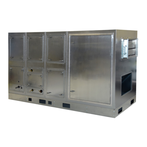
- Page 1 DN-Series DOAS Indoor INSTALLATION, OPERATION & MAINTENANCE MANUAL FOR COMMERCIAL APPLICATIONS Model DN-2-JIN Shown WWW.RENEWAIRE.COM...
- Page 2 DN-Series DOAS Indoor IMPORTANT SAFETY INFORMATION WARNING CAUTION ARC FLASH AND ELECTRIC SHOCK HAZARD RISK OF CONTACT WITH HOT SURFACES Arc flash and electric shock hazard. Disconnect all electric The blower motor and other electrical components are extremely power supplies, verify with a voltmeter that electric power is off hot during operation.
-
Page 3: Dn Doas Unit Information
DN-Series DOAS Indoor IMPORTANT USER INFORMATION SAVE THIS MANUAL NOTICE This manual contains space for maintaining written records of unit maintenance and / or repairs. See Section 12.0 Maintenance Records. At the time the DOAS is commissioned, a maintenance schedule should be developed by the user to incorporate monthly and seasonal maintenance and include start-up maintenance tasks as described in this manual. -
Page 4: Table Of Contents
DN-Series DOAS Indoor TABLE OF CONTENTS 3.3 DOAS DN-5 DIMENSIONED DRAWING 3.4 DOAS DN-2 CORNER WEIGHTS INSTALLATION, OPERATION & MAINTENANCE 3.5 DOAS DN-3 CORNER WEIGHTS MANUAL 3.5 DOAS DN-5 CORNER WEIGHTS 4.0 SHIPPING / RECEIVING / HANDLING DN DOAS UNIT INFORMATION 4.1 UNIT WEIGHTS / DIMENSIONS... - Page 5 DN-Series DOAS Indoor 10.0 MAINTENANCE 10.1 MAINTENANCE 24 HRS. AFTER START-UP 10.2 MAINTENANCE 30 DAYS AFTER START-UP 10.3 MAINTENANCE SCHEDULE 10.4 FILTERS 10.5 SERVICE PARTS 11.0 MAINTENANCE REFERENCE 11.1 CABINET MAINTENANCE 11.2 ELECTRIC MOTOR MAINTENANCE 11.2.1 Motor Cleanliness 11.2.2 VFDs (optional) 11.3 ENTHALPIC CORE MAINTENANCE...
- Page 6 Electric Heater (typical) Water Coil (typical) Electric Heater Control Panel (typical) RenewAire Commercial Controller Premium Commercial Controls Installed RenewAire Commercial Controller Expansion Board Carbon Dioxide Sensor, Wall Mount Time Clock, Panel Mount IAQ Sensor, Wall Mount Time Clock, Exterior Enclosure...
-
Page 7: Renewaire Configuration Code
17: SA Fan Location Code "A" is not available when no coils are selected. 18: SA Fan Location Code "B" is not available when only coils are selected for Heating and Cooling and Orientation Codes are "B", "D", "F", "J", "K", "N", "P" or "V". DN-Series Configuration Code Chart 1.800.627.4499 INSTALLATION, OPERATION AND MAINTENANCE MANUAL RENEWAIRE.COM... -
Page 8: Overview
OVERVIEW DN-Series DOAS Indoor 1.0 OVERVIEW 1.1 DESCRIPTION This unit is an indoor Dedicated Outdoor Air System (DOAS) that provides makeup air that is optionally NOTE: This unit is a heated, cooled and dehumidified to a conditioned space. The air that is drawn through the unit also Dedicated Outdoor Air goes through enthalpic cores to recover energy from exhaust air. -
Page 9: Dn Doas Modules
OVERVIEW DN-Series DOAS Indoor ENERGY RECOVERY CONTROLS EA FAN MODULE MODULE MODULE Bypass and Filter HEAT MODULE SA FAN MODULE COIL MODULE Assys Shown (gas heater (shown in fan-be- DX Coil, HGRH Shown) fore-coil position) Shown (may be moved before fan) -
Page 10: Airflows
OVERVIEW DN-Series DOAS Indoor 1.3 AIRFLOWS The DOAS has many configurations available for airflow inlet and/or outlet. The customer is to select each individual airstream location and then apply all four locations to the matrix at right, selecting the one example that fits all criteria. The identifying letter beneath each figure is shown on the configura- tion code. - Page 11 OVERVIEW DN-Series DOAS Indoor KEY TO CONFIGURATION CODES CODE Intake Vertically (through unit roof) Discharge Horizontally Discharge Horizontally (through unit side wall) (through unit side wall) Intake Horizontally (through unit end wall) EA Fan EA Fan Discharge Horizontally Discharge Horizontally...
- Page 12 OVERVIEW DN-Series DOAS Indoor Intake Vertically (through unit roof) Discharge Horizontally Discharge Horizontally (through unit side wall) (through unit side wall) Intake Horizontally (through unit end wall) EA Fan EA Fan Discharge Horizontally Discharge Horizontally (through unit end wall) (through unit end wall)
- Page 13 OVERVIEW DN-Series DOAS Indoor Intake Vertically (through unit roof) Discharge Vertically Discharge Vertically (through unit roof) (through unit roof) Intake Horizontally (through unit end wall) EA Fan EA Fan Intake Horizontally Intake Horizontally SA Fan SA Fan (through unit end wall)
-
Page 14: Doas Internal Airflow Configuration
OVERVIEW DN-Series DOAS Indoor 1.3.2 DOAS Internal Airflow Configuration Within the DOAS, airstreams can be redirected as a result of changes in the bypass or recirculation dampers. In normal operation, typical airflow is through the enthalpic cores and then through the fan module. -
Page 15: Plan View Of Typical Airflow Through Dn Doas
OVERVIEW DN-Series DOAS Indoor PLAN VIEW TYPICAL OF SMALL AND MEDIUM CABINETS Plan View, Typical of DN-2 and DN-3 Models PLAN VIEW TYPICAL OF SMALL AND MEDIUM CABINETS Bypass (Economizer)/ Bypass Recirculation Assembly Damper Bypass (Economizer)/ (closed) Bypass Recirculation Assembly... -
Page 16: Dampers
OVERVIEW DN-Series DOAS Indoor 1.4 DAMPERS Class I airfoil dampers are standard on all units. OA, EA, face and bypass dampers come as standard and a recirculation damper is optional. All dampers are operated by 24 VAC electric actuators. The actuators are mounted on the inside of the unit. -
Page 17: Heating
The heater control module is controlled by an analog signal from the controller. See illustration below. See the RenewAire Electric Heater Module User Manual for further information. -
Page 18: Cooling
It is the user’s responsibility to assess supply water conditions and verify suitability for use. In addi- tion, it is the user’s responsibility to winterize the water lines as needed. RenewAire does not make any recommendations regarding minimum quality of cooling water nor for any treatments that may be needed. -
Page 19: Component Description
COMPONENT DESCRIPTION DN-Series DOAS Indoor 2.0 COMPONENT DESCRIPTION 2.1 CABINET CONSTRUCTION • The DOAS is available in either single-thickness (1”) wall or double-thickness (2” thick, with thermal break) wall construction. See Digit 11 of the Configuration Code. • The sheet metal exterior of the unit is 20 gauge galvanized steel. -
Page 20: Fan Speed Control
Electric heater modules are always installed in the lower part of the DOAS heat module and is always downstream of the fans. See Digit 18 of the DOAS configuration code. Also see the specific configuration code for electric heater modules, as shown in RenewAire Electric Heater Module User Manual. -
Page 21: Split Dx Cooling (Optional)
COMPONENT DESCRIPTION DN-Series DOAS Indoor Solid State Relay (SSR) Airflow Proving Switch Electric Heater (typical) Electric Heater Control Panel (typical) 2.9 SPLIT DX COOLING (OPTIONAL) All units that are ordered with optional split DX cooling have a factory-installed DX coil. The coil is charged with nitrogen gas and is to be purged by the installer. -
Page 22: Controls
RenewAire DN DOAS Integral Commercial Controls User Manual. 2.12.1 Microprocessor Commercial Controls All DN DOAS units are equipped with RenewAire Premium Commercial Controls. The controller is a multi-function device that monitors operation of the DOAS and air conditions. It evaluates conditions such as temperatures, air pressures, air flows and air quality and then modulates the operation of the air handler to meet owner-specified set points. -
Page 23: Optional Control Accessories
DN-Series DOAS Indoor 2.13 OPTIONAL CONTROL ACCESSORIES RenewAire offers a number of control accessories as options that are to be field-installed and wired directly to the low voltage terminal strip. See Section 6.6.5 of this manual. Depending on how the Commercial Controller is programmed by the user, each device functions either as an ON/OFF switch for the DOAS, or it will modulate the DOAS. -
Page 24: Motion Occupancy Control
COMPONENT DESCRIPTION DN-Series DOAS Indoor 2.13.4 Motion Occupancy Control A motion occupancy sensor is available as an optional control device in either ceiling mount or wall mount styles. These sensors can be wired directly to the low voltage terminal strip in the DOAS and function as ON/OFF controllers. -
Page 25: Unit Drawings
DIMENSIONED DRAWINGS DN-Series DOAS Indoor 3.0 UNIT DRAWINGS 3.1 DOAS DN-2 DIMENSIONED DRAWING DOAS DN-2 Dimensions 1.800.627.4499 INSTALLATION, OPERATION AND MAINTENANCE MANUAL RENEWAIRE.COM... -
Page 26: Doas Dn-3 Dimensioned Drawing
DIMENSIONED DRAWINGS DN-Series DOAS Indoor 3.2 DOAS DN-3 DIMENSIONED DRAWING DOAS DN-3 Dimensions RENEWAIRE.COM INSTALLATION, OPERATION AND MAINTENANCE MANUAL 1.800.627.4499... -
Page 27: Doas Dn-5 Dimensioned Drawing
DIMENSIONED DRAWINGS DN-Series DOAS Indoor 3.3 DOAS DN-5 DIMENSIONED DRAWING DOAS DN-5 Dimensions 1.800.627.4499 INSTALLATION, OPERATION AND MAINTENANCE MANUAL RENEWAIRE.COM... -
Page 28: Doas Dn-2 Corner Weights
DIMENSIONED DRAWINGS DN-Series DOAS Indoor 3.4 DOAS DN-2 CORNER WEIGHTS DN-2-IN 1" CABINET UNIT WEIGHTS (LBS) MODELS UNIT 70.86 36.85 23.69 1250 ERV + Coil 95.36 51.51 22.9 1750 ERV + EH 95.36 47.21 23.18 1600 DN-2-IN ERV + GH 95.36... -
Page 29: Doas Dn-5 Corner Weights
DIMENSIONED DRAWINGS DN-Series DOAS Indoor 3.5 DOAS DN-5 CORNER WEIGHTS DN-5-IN 1" CABINET UNIT WEIGHTS (LBS) MODELS UNIT 78.04 39.23 44.51 2600 ERV + Coil 109.78 53.08 44.58 3300 DN-5-IN ERV + EH 136.26 61.09 44.29 3550 1005 ERV + GH 136.26... -
Page 30: Shipping / Receiving / Handling
All DOAS units are palletized and then shipped by common carrier. It is the installer’s / customer’s responsibility to coordinate delivery and properly handle the shipment during unloading and storage. RenewAire also provides a model-specific manual for shipping, rigging, lifting and assembly that is also available online at www.renewaire.com. -
Page 31: Receiving
4.3 RIGGING For rigging instructions, refer to the model-specific manual for shipping, rigging, lifting and assembly that is also available online at www.renewaire.com. 4.4 HANDLING AND STORAGE Upon delivery to a job site, the DOAS should ideally be placed and installed immediately. If the unit cannot be installed immediately, it should be protected from the weather, either by moving it indoors or by covering with tarps. -
Page 32: Installation
6.0 INSTALLATION 6.1 CURB ASSEMBLY AND PLACEMENT Curbs are not normally required or used for indoor installations of the RenewAire DOAS. 6.2 UNIT PLACEMENT DOAS location is normally specified by others but installers must also verify that the installation is in accordance with all local codes and building regulations. -
Page 33: Factory-Recommended Gas Service Entry
DN-Series DOAS Indoor 6.5 GAS REQUIREMENTS (IF EQUIPPED WITH A GAS HEAT MODULE) Gas requirements are detailed in the RenewAire Integral Indirect Gas-Fired Heat Module User Manual. 6.5.1 Factory-Recommended Gas Service Entry All DOAS units that are equipped with an indirect-fired gas furnace are to have gas supply connected in accordance with instructions with RenewAire Indirect Gas-Fired Heat Module User Manual supplied with this unit. -
Page 34: High Voltage Supply Circuits
ELECTRICAL CONNECTIONS DN-Series DOAS Indoor 6.6.3 High Voltage Supply Circuits This DOAS uses a single-point high voltage electrical supply connection. All wires are to be terminated at the same point on the top of the disconnect switch. See photo below. Depending on the ampacity of the unit, different disconnect switches may be used, but high voltage supply wiring is always terminated at the top of the disconnect switch. -
Page 35: Low Voltage Electrical Connections
ELECTRICAL CONNECTIONS DN-Series DOAS Indoor 6.6.4 Low Voltage Electrical Connections 6.6.5 Low Voltage Terminal Blocks There are six low voltage terminal blocks located in the E-Box; 4 gray, 1 white and 1 black. Only the gray terminal block labeled with numbers 31 - 40 is used to terminate optional control sensors. -
Page 36: Piping Connections
PIPING CONNECTIONS DN-Series DOAS Indoor 6.7 PIPING CONNECTIONS 6.7.1 Coil Connections Piping connections to DOAS coils may be water coil (either heating or cooling), steam coil or refrigerant for a DX cooling coil or a HGRH coil Fluid coils are located in the coil module which may be either upstream or downstream of the SA fan module. -
Page 37: Drain Traps
1” diameter stainless steel with female NPT. The image below shows the underside of the drain fitting. For specific information on trapping a gas furnace condensate drain, see the RenewAire Integral Indirect Gas-Fired Heat Module User Manual. For instructions on designing both positive and negative pressure drain traps, see Section 6.7.4 Drain Trap Construction in this manual. - Page 38 PIPING CONNECTIONS DN-Series DOAS Indoor When the SA fan module is located upstream of the cooling module, the resulting pressure sensed at the condensate pan will be POSITIVE. See below. Coil Module SA Fan Module SA fan module located before the coil module.
-
Page 39: Drain Trap Construction
For all drain traps, RenewAire recommends the installation of threaded plugs at several locations to permit periodic cleaning and filling of the trap. Also recommended is the use of a vacuum breaker if water is being discharged from the trap into a drain pipe. -
Page 40: Waterless Drain Traps
6.7.5 Waterless Drain Traps As an alternative to a field-fabricated and installed condensate P-trap, RenewAire offers an HVAC waterless trap. The advantages to a waterless trap are that they may require less vertical clearance for (negative pressure) installations, they generally do not require winterization and they do not require priming at the beginning of the cooling season. -
Page 41: Type "P" Positive Pressure Waterless Trap
PIPING CONNECTIONS DN-Series DOAS Indoor 8” Allow clearance for 1” sweep at top and bottom of the trap. Also allow vertical clearance for a screen-union, if used. Follow manufacturer’s instructions for installation. Type “P” Positive Pressure Waterless Trap 5 - 5/8”... -
Page 42: Wiring Schematics
WIRING SCHEMATICS DN-Series DOAS Indoor 6.8 WIRING SCHEMATICS 6.8.1 Typical Input Power This wiring schematic is TYPICAL of single phase, input for model DN- 2. This drawing is for a unit that includes gas heat and EC motors. A unit-specific... -
Page 43: Three Phase Power Wiring Schematic
WIRING SCHEMATICS DN-Series DOAS Indoor This wiring schematic is TYPICAL of three phase, 208-230 and 460 VAC input for models DN-2 and DN-3. This drawing is for a unit that includes gas heat and EC motors. A unit-specific electrical schematic is to be found inside the access door to the unit control module. -
Page 44: Three Phase Power Wiring Schematic
WIRING SCHEMATICS DN-Series DOAS Indoor This wiring schematic is TYPICAL of three phase, 208-230 and 460 VAC input for model DN-5. This drawing is for a uniN-t that includes gas heat and EC motors. A unit- specific electrical schematic is to be found inside the access door to the unit control module. -
Page 45: Typical Control Wiring
WIRING SCHEMATICS DN-Series DOAS Indoor 6.8.2 Typical Control Wiring This wiring schematic is TYPICAL control wiring for a three phase, 208-230 and 460 VAC input for models DN-2, DN-3 and DN-5. This drawing is for a unit that includes gas heat and EC motors. -
Page 46: Typical Field Wiring
WIRING SCHEMATICS DN-Series DOAS Indoor 6.8.3 Typical Field Wiring This wiring schematic is TYPICAL of three phase, 208-230 and 460 VAC input for models DN-2, DN-3 and DN- 5. This drawing is for a unit that includes gas heat and EC motors. -
Page 47: Control Connections
CONTROL CONNECTIONS DN-Series DOAS Indoor 6.9 CONTROL CONNECTIONS Control wiring is to enter the E-Box at the front of the E-Box and is then terminated on the field wiring low voltage terminal strip. See Section 6.6.5 Low Voltage Terminal Blocks for further information. -
Page 48: Points List
CONTROL CONNECTIONS DN-Series DOAS Indoor 7.2 POINTS LIST The points list is to be found in the DOAS Integrated Programmable Controls manual. CAUTION RISK OF DAMAGE TO POWER SUPPLY AND CONNECTED COMPONENTS UNITS WITH 230 VAC POWER SOURCE: The DOAS is shipped from the factory with the transformers set for 208 VAC primary power. If the actual power source is 230 VAC, move the black primary-side lead from the transformer’s “208 V”... -
Page 49: External Control Connections
CONTROL CONNECTIONS DN-Series DOAS Indoor 7.3 EXTERNAL CONTROL CONNECTIONS External control wiring is to be terminated on the low voltage terminal strip in the E-Box as shown in the unit-specific wiring diagram to be found in the unit. 7.4 SEQUENCE OF OPERATION... -
Page 50: Pre Start-Up
PRE START-UP DN-Series DOAS Indoor 8.0 PRE START-UP 8.1 VERIFY VOLTAGES Using a voltmeter, test the input voltages as supplied to the disconnect switch. Refer to Digit 13 of the unit Configuration Code to find the rated voltage. The supplied voltage must be within +/- 10% of the rated voltage. -
Page 51: Maintenance
MAINTENANCE DN-Series DOAS Indoor 10.0 MAINTENANCE RenewAire DOASs are built to operate with minimal maintenance. After unit commissioning, the primary areas of attention are the air filters. 10.1 MAINTENANCE 24 HRS. AFTER START-UP 24 hours after unit start-up: • If unit has DX or cooling coils, inspect for water where it does not belong. Inspect the conden- sate pan and trap to make sure condensate is draining properly. -
Page 52: Service Parts
MAINTENANCE DN-Series DOAS Indoor 10.5 SERVICE PARTS DOAS Service Parts RENEWAIRE.COM INSTALLATION, OPERATION AND MAINTENANCE MANUAL 1.800.627.4499... -
Page 53: Maintenance Reference
MAINTENANCE REFERENCE DN-Series DOAS Indoor 11.0 MAINTENANCE REFERENCE Maintenance of this unit has a split schedule. It is broken down into Monthly, Semi Annual and Annual tasks and the schedule must be adjusted for heating or cooling. If there is a cooling system in the unit, the annual maintenance for the cooling system should be scheduled for the start of the cooling season. -
Page 54: Electric Motor Maintenance
MAINTENANCE REFERENCE DN-Series DOAS Indoor 11.2 ELECTRIC MOTOR MAINTENANCE The most important issue in motor maintenance is motor cleanliness. 11.2.1 Motor Cleanliness Removing dust and grease buildup on the motor housing assists proper cooling. Never wash-down the motor with high pressure spray. -
Page 55: Enthalpic Core Maintenance
MAINTENANCE REFERENCE DN-Series DOAS Indoor 11.3 ENTHALPIC CORE MAINTENANCE The enthalpic core media is a fibrous material that must be kept clean at all times. As a minimum, cores should be cleaned once per year. • DO NOT WASH OR ALLOW THE ENTHALPIC CORES TO GET WET. -
Page 56: Fan / Motor Removal
MAINTENANCE REFERENCE DN-Series DOAS Indoor 11.4 FAN / MOTOR REMOVAL Each EC motor and fan are part of an assembly that is mounted on an air inlet cone. If a fan or EC fan motor should require servicing or replacement, the entire assembly should be removed from the DOAS. - Page 57 MAINTENANCE REFERENCE DN-Series DOAS Indoor Each asynchronous motor and fan are part of an assembly that is mounted on a sled. If a fan or fan motor should require servicing or replacement, the fan and motor should be unbolted from the sled in order to remove it from the DOAS.
-
Page 58: Coils
MAINTENANCE REFERENCE DN-Series DOAS Indoor 11.5 COILS 11.5.1 Coil Maintenance / Removal The primary maintenance issue with coils is “housekeeping”. Periodic inspection of all coils is needed Whenever using to search for bent fins which will impede air flow and inspect for cleanliness which reduces the cleaning agents in- efficiency of the coil. -
Page 59: Door Latch Adjustment
MAINTENANCE REFERENCE DN-Series DOAS Indoor 11.6 DOOR LATCH ADJUSTMENT With age and use, the door gaskets may become compressed and no longer provide a complete seal against air leakage. The door latches can be easily adjusted by changing the position of the swing arm on the inside of the door. -
Page 60: Water Treatment Maintenance
DN-Series DOAS Indoor 11.9 WATER TREATMENT MAINTENANCE RenewAire does not make any recommendations regarding minimum water quality for user-supplied water in the DOAS coils. If the user is employing a water treatment system, observe the instructions provided with the specific treatment system. -
Page 61: Damper Maintenance
To contact RenewAire Customer Service: Call 800-627-4499 RenewAireSupport@RenewAire.com Email: Remember that RenewAire Customer Service can only assist with the products sold by RenewAire, it cannot resolve engineering issues that result from air handling system design by others. 1.800.627.4499 INSTALLATION, OPERATION AND MAINTENANCE MANUAL... -
Page 62: Maintenance Records
MAINTENANCE REFERENCE DN-Series DOAS Indoor 12.0 MAINTENANCE RECORDS Also see the User Manuals for any included options such as a gas heater, DX cooling, etc. AIR FILTER REPLACEMENT RECORD FILTERS REPLACED DATE: ENTHALPIC CORES CLEANING RECORD CORES CLEANED DATE: RENEWAIRE.COM INSTALLATION, OPERATION AND MAINTENANCE MANUAL 1.800.627.4499... - Page 63 MAINTENANCE REFERENCE DN-Series DOAS Indoor ELECTRIC HEAT OR GAS HEAT MODULE MAINTENANCE RECORD MODULE MAINTENANCE DATE: DX COIL MAINTENANCE RECORD COILS CLEANED DATE: UNIT WINTERIZATION RECORD WINTERIZATION DATE: 1.800.627.4499 INSTALLATION, OPERATION AND MAINTENANCE MANUAL RENEWAIRE.COM...
- Page 64 A BOU T RENEWAI RE For over 30 years, RenewAire has been a pioneer in enhancing indoor air quality (IAQ) in commercial and residential buildings of every size. This is achieved while maximizing sustainability through our fifth-generation, static-plate, enthalpic-core Energy Recovery Ventilators (ERVs) that optimize energy efficiency, lower capital costs via load reduction and decrease operational expenses by minimizing equipment needs, resulting in significant energy savings.
Need help?
Do you have a question about the DN-Series and is the answer not in the manual?
Questions and answers