Table of Contents
Advertisement
Quick Links
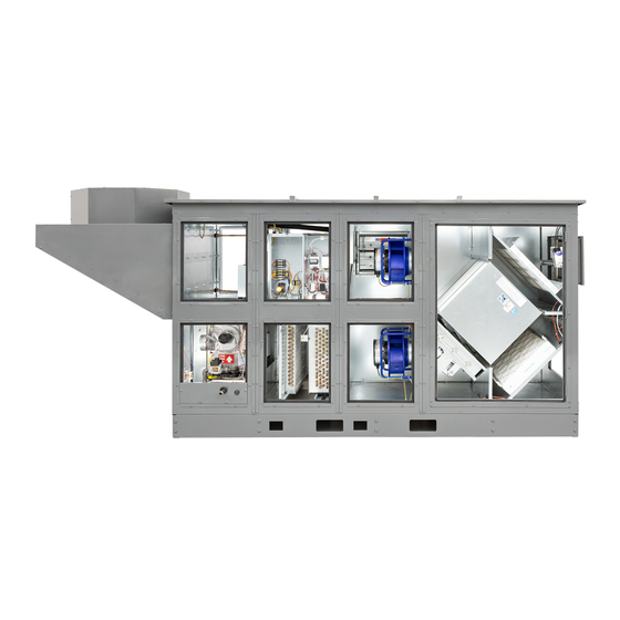
DN SERIES DOAS
Start-up Guide
To insure the quality of the installation and the proper operation of this unit, the following Start-Up routines should be completed. Please follow
the procedures and recommendations identified in this report and record start-up information in the specified areas. If a problem with the unit
becomes apparent, correct the problem by referring to the installation manual or contact the Factory Representative for further assistance.
Please verify the accuracy of all model and serial number information before contacting the manufacturer.
JOB NAME:
MODEL NO:
CONTRACTOR:
This unit should be started up for a brief period immediately after high and low-voltage wiring are complete. The purpose of the
initial start-up is only to verify correct fan rotation direction and that the dampers are opening and closing properly. After the unit
has been run for a brief period, it is to be shut back down until the entire installation is complete. The unit is not to be used for
building ventilation before the building has been completed.
PRIOR TO UNIT START-UP:
Installation of unit and electrical wiring must be done by a qualified professional(s) in accordance with all applicable codes,
standards and licensing requirements. Before servicing or cleaning the unit, switch power "off" at the disconnect switch or
building service panel and lock-out/tag-out to prevent power from being accidentally turned on. This unit must be grounded as
per instructions.
The unit must be in its final location.
Verify all prefilters are in place and on the correct airstreams (i.e. inlet face of core exhaust and the inlet face of the core
supply) if previously removed.
High-voltage supply wiring must be complete.
All low-voltage wiring, including field-installed sensors, must be completed to the correct numbered terminal on the low-
voltage terminal blocks.
All debris or construction materials must be removed from the unit.
All doors and access panels must be in place.
Initial start-up should not be performed if the air is laden with construction dust. Filters will quickly become dirty and require
changing for other subsequent testing.
If this unit was purchased with a Remote User Terminal (RUT) for the controller, connect the RUT and perform start-up steps
with the RUT. If there is no RUT, perform the start-up steps by using the buttons on the Integrated Programmable Controller or
the internal web pages.
Make sure all power to the unit is "off" and all disconnects are in the "off" position before making final power connections
FOR INDOOR UNITS: Confirm that the supply and exhaust vent connections have been properly connected and the penetration
points have been separated by a minimum of 10', are free of obstructions, and are screened and properly terminated as per
directions. Inspect the OA and EA vent pipes to confirm that they are pitched ¼" per foot away from the unit and insulated
with vapor barrier insulation.
FOR ROOF TOP UNITS: Inspect and confirm that all ductwork has been connected and sealed as per installation instructions.
Confirm circuit breaker amperage does not exceed the MOP on the nameplate and verify the unit is wired with the correct
line voltage.
Spin each blower wheel to assure they are not rubbing and are in alignment in the blower housing.
Check all set screws and fasteners on blowers, bearings, sheaves, and drives (if adjustments have been made) to
assure tightness.
CAUTION
CAUTION
RISK OF ELECTRIC SHOCK OR EQUIPMENT DAMAGE
Whenever electrical wiring is connected, disconnected or
changed, the power supply to the unit and its controls must
be disconnected. Lock and tag the disconnect switch or
circuit breaker to prevent accidental reconnection of
electric power.
TAG:
SERIAL NO:
TESTED BY:
WARNING
RISK OF CONTACT WITH HIGH-SPEED MOVING PARTS.
Disconnect all local and remote power supplies, verify with
a voltmeter that electric power is off and all fan blades have
stopped rotating before working on the unit.
Do not operate this unit with any cabinet panels removed.
DATE:
CAUTION
Advertisement
Table of Contents

Subscribe to Our Youtube Channel
Related Manuals for RenewAire DOAS DN Series


Summary of Contents for RenewAire DOAS DN Series
- Page 1 DN SERIES DOAS Start-up Guide To insure the quality of the installation and the proper operation of this unit, the following Start-Up routines should be completed. Please follow the procedures and recommendations identified in this report and record start-up information in the specified areas. If a problem with the unit becomes apparent, correct the problem by referring to the installation manual or contact the Factory Representative for further assistance.
-
Page 2: Control Menu Structure
ARC FLASH AND ELECTRIC SHOCK HAZARD All RenewAire models operate on high voltages that can cause severe electric shock. Some models use high voltages that are capable of causing dangerous arc flash. Whenever accessing any part or component of the unit, disconnect all electric power supplies, verify with a voltmeter that electric power is OFF and wear protective equipment per NFPA 70E when working within the electric enclosure. - Page 3 DOAS Start-up Guide SET THE TIME AND UNIT OF MEASURE The controller needs the correct time and date for alarm stamps, etc. The unit of measure setting will determine the values that show on the display. CONFIRM THE CONFIGURATION Using these two screens, confirm that the unit has the correct configuration. ADD ANY REQUIRED SENSORS Address Ext Baud Prot...
- Page 4 Address Ext Baud Prot 19.2 K 9.6 K with o set 38.4 K CAREL no o set 57.6 K Modbus DOAS Start-up Guide Address Ext. Baud Prot 19.2 K 9.6 K Address Ext Baud Prot with o set 38.4 K CAREL EXPANSION MODULE no o set...
- Page 5 DOAS Start-up Guide CONFIGURE AIRFLOW FOR SUPPLY AND RETURN FANS If you choose constant speed fan control, you will be allowed to set the variable speed fans to a specific fan speed as a percentage. You will have these additional options. Choose your type and set the corresponding settings for that type.
-
Page 6: Unit Start-Up
DOAS Start-up Guide Repeat for exhaust fan. UNIT START-UP: Start the unit through the keypad. The digital input ID1 (terminals 17 to 18) has to be closed. See the images on the below. The unit is now powered up and the dampers should begin moving. Once the dampers are in their programmed positions, the fans will begin to run. - Page 7 DOAS Start-up Guide Observe this status screen for status of fans and unit. All four answers should be “YES” and the Unit should show UNIT ON. If the Fan On is NO when the fans are running the current switch for that fan needs to be adjusted. Shut down the unit by switching UNIT ON/OFF back to OFF and turning the disconnect switch to OFF.
-
Page 8: Refrigerant Circuits
DOAS Start-up Guide COOLING CHECKOUT Observe the cooling behavior in the status screens. IF THE UNIT DOES NOT HAVE PACKAGED DX, PROCEED TO HEATING. If the unit has packaged DX continue with the following steps. ADDITIONAL STEPS FOR PACKAGED DX UNITS Observe in this screen that the unit runs at the desired speed once the startup time elapses. - Page 9 DOAS Start-up Guide For units with two refrigerant circuits, continue to lower temperature setpoint until the second circuit comes on if the environmental conditions allow. (If not, see Verify Second Circuit Manually section.) COMP2 ON/OFF STATUS Once settled, record the values on these screens. The expected suction superheat should be around 12°F. If it is far from this value, observe the sight glass to determine whether the refrigerant change needs to be adjusted.
- Page 10 DOAS Start-up Guide Once settled, record the values on these screens. The expected suction superheat should be around 12°F. If it is far from this value, observe the sight glass to determine whether the refrigerant change needs to be adjusted. REFRIGERANT CIRCUITS DISCHARGE DISCHARGE...
- Page 11 DOAS Start-up Guide SET THE HEATING SETTINGS Confirm that the correct heating type is set. Make sure the connections are physically in place. Choose to control to the heating setpoint or to a reset schedule with outdoor air. Choose between control off supply or return air. Be sure to make sure the outdoor air lockout temperature is below the current outdoor temperature.
-
Page 12: Optional Settings
E.S.P. E.S.P. (FA) CFM R.P.M. (FA) CFM R.P.M. MOTOR AMPS (OA) MOTOR AMPS (EA) (MIN CIR. AMPS) (MAX FUSE SIZE) UNIT LINE VOLTAGE VOLTAGE: L1-L2 L2-L3 L3-L1 Member of the S&P Group 2021 © RenewAire LLC Family of Brands 133977_001_NOV21...
Need help?
Do you have a question about the DOAS DN Series and is the answer not in the manual?
Questions and answers