Advertisement
Quick Links
Installation Instructions for
FIB1-10/100 Family 10/100BASE-TX / 100BASE-FX
Fiber Transceiver Converters
Description
The FIB1 Family are standalone fiber media converters available in a number of different models that also act as line
cards for placement in the FRM301 Platform Media Converter Chassis. The FIB1-10/100 is a media converter for
10Base-T or 100Base-TX, data transmission over optical fiber media depending on your specific network needs. .
All media converters are available with either multi-mode or single-mode optical transceivers and with connectors
for SC, ST or FC. In single mode, WDM (Wave Division Multiplexing with SC connector) is also available in 20 or
40KM reach, which will provide the ability to transmit and receive data using only a single optical fiber. When the
FIB1-10/100 card is placed in the FRM301 rack with SNMP management, the card status, type, version, fiber link
status, data link status and alarms can all be displayed. For the UTP side, auto-negotiation is default. These units will
automatically tailor themselves to convert both half-duplex or full-duplex signals and You may also set the FX side
in full-duplex only or half-duplex only. The Fiber Transceiver Converters give you the freedom to extend your
10/100Mbps cabling distance by allowing connectivity up to 120 kilometers. Six LED indicators signal the power
status of the converter, UTP port speed, duplex status and Link/RX and FX port Link/RX and duplex status.
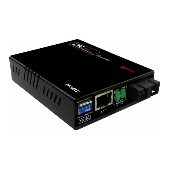
DC Jack
Ethernet Connections
Front Panel DIP Switch Setting
1.Full /Half : The Fiber Duplex will be configured in Full-duplex or Half-duplex
* This switch has included an "Auto Reset" function so the power-reset is not
necessary when any modification is made here.
2. Loop-back test and get remote side status ( NORM
* If the Local side loop-back test is active then LEDs (except the PWR LED) will
all blink rapidly and refresh to display the remote side status.
**Note: This application must be run under the circumstance that the remote side
loop-back testing function is off.
Fiber Connections
LEDs
DIP Switches
Not active ; LBT ON active )
Specifications
Standard
IEEE802.3 10BASE-T, IEEE802.3u 100BASE-TX, l00BASE-FX (Fast Fiber, 100Mbps)
Supports Full Duplex Ethernet mode (200Mbps)
FIB1-10/100 family supports transmission of Ethernet packet up to 1600 Bytes in size.
10/100BASE-TX RJ-45 Connectors
One RJ-45 connector is provided auto MDI/X function for connection to either MDI-X (To PC) or MDI (To HUB)
equipment. This allows all UTP connections to be made using only a common straight-through UTP cable.
RJ-45 Pin
MDI type
1
Tx+
2
Tx-
3
Rx+
6
Rx-
10/100BASE-TX UTP Cable
Cable type: 10Base-T; Cat. 3,4 or 5 ; 100Base-Tx; Category 5
Maximum cable distance: 100 meters (328 feet)
Fiber Optic Connectors
For FIB1-10/100:
Two connectors are provided for fiber optic cable connection.
One is for transmission and the other is for reception of optical data
For FIB1-10/100W: One connector is provided for fiber optic cable connection.
For both transmission and reception of optical data.
Please note that transceiver "A" must connect to transceiver
"B" for proper fiber linking.
LED Indicators
LED
Function
State
Status
PWR
Power indicator On
Converter has power
Off
Converter has no power
Fiber Full
Mode display
On
Fiber side full duplex mode (200mbps)
Off
Fiber side half-duplex mode
Fiber Link Fiber link
On
The fiber link is ok.
Off
No link or the link is faulty.
Blinking Receiving data on the fiber.
LAN 100
Mode display
On
UTP side is operating in 100Mbps mode.
Off
UTP side is operating in 10Mbps mode
LAN Full
Mode display
On
UTP side full duplex mode (200mbps).
Off
UTP side half-duplex mode
LAN Link Ethernet link
On
The UTP link is ok.
Off
No link or the link is faulty.
Blinking Receiving data on Ethernet.
Environment
Temperature : 0℃ - 70℃
Humidity
10-90% non condensing
Dimension
122.6mm x 85.6mm x 20mm
(H x W x D)
Power
+9V /1A maximum
DC Plug Type : Center Positive
V.: 1.4
Advertisement

Subscribe to Our Youtube Channel
Related Manuals for CTC Union FIB1-10/100 series


Summary of Contents for CTC Union FIB1-10/100 series
-
Page 1: Specifications
Installation Instructions for Specifications FIB1-10/100 Family 10/100BASE-TX / 100BASE-FX Standard Fiber Transceiver Converters IEEE802.3 10BASE-T, IEEE802.3u 100BASE-TX, l00BASE-FX (Fast Fiber, 100Mbps) Supports Full Duplex Ethernet mode (200Mbps) Description FIB1-10/100 family supports transmission of Ethernet packet up to 1600 Bytes in size. The FIB1 Family are standalone fiber media converters available in a number of different models that also act as line cards for placement in the FRM301 Platform Media Converter Chassis. - Page 2 Dip Switch Settings (on PCB) Loop-back Testing(LBT)& Get CPE status Application Note : (Observe the “ON” marking on the DIP switch. All “Off” is the default position. Except the dip switch #5. Any ( While this feature is operating the fiber side transmission will be halted ) changes to the default settings require opening the case.
Need help?
Do you have a question about the FIB1-10/100 series and is the answer not in the manual?
Questions and answers