Table of Contents
Advertisement
Advertisement
Table of Contents

Related Manuals for CTC Union FMC-100M


Summary of Contents for CTC Union FMC-100M
- Page 1 USER MANUAL FMC-100M(S) Fast Ethernet OAM/IP Web Smart Media Converter...
- Page 2 Fast Ethernet OAM/IP Web Smart Media Converter Version 1.1 August 2015 (Update) This Manual supports the following models: FMC-100M : 1x100Base-FX + 1x10/100Base-TX FMC-100MS : 1x100Base-FX (SFP) + 1x10/100Base-TX 2015 CTC Union Technologies Co., LTD. All trademarks are the property of their respective owners.
- Page 3 CTC Union Technologies reserves the right to make changes in its products or product specifications with the intent to improve function or design at any time and without notice and is not required to update this documentation to reflect such changes.
-
Page 4: Table Of Contents
Table of Contents CHAPTER 1 INTRODUCTION ................................................6 1.1 W ........................................................ 6 ELCOME 1.2 P ....................................................6 RODUCT ESCRIPTION 1.3 P ....................................................7 RODUCT EATURES 1.4 S ......................................................8 PECIFICATIONS 1.5 M ................................................... 8 ANAGEMENT EATURES 1.6 P ........................................................9 ANEL 1.7 LED I ..................................................... - Page 5 3.1.6.9 Q in Q Configuration ......................................................24 3.1.7 Remote Settings ..................................................25 3.1.8 802.3ah OAM Functions................................................25 3.1.8.1 802.3ah Configuration ....................................................... 26 3.1.8.2 Loop back Test ........................................................27 3.1.8.3 802.3ah Status ........................................................28 3.1.9 Tools ......................................................30 3.1.9.1 System Reboot ........................................................31 3.1.9.2 Save and Restore .......................................................
-
Page 6: Chapter 1 Introduction
Thank you for choosing FMC-100M(S) Fast Ethernet OAM/IP Web Smart Media Converter. Throughout this document, the two different models of this family will be referred to as FMC-100M(S) or in an abbreviated form as just 100M(S). If you would like to skip right to the installation of the converter, proceed to Chapter 2. -
Page 7: Product Features
Supports DHCP client for automatic TCP/IP configuration FMC-100M(S) SFP socket supports a wide range of standard SFP modules to address any network situation. Single-mode, Multi-mode, Multi-rate, Single fiber bi-directional, Coarse and Dense Wave Division Multiplexing (CWDM and DWDM) and... -
Page 8: Specifications
1.4 Specifications Optical Interface Connector Duplex SC, ST, FC (100M) or SFP cage (100MS) Data rate 100Base-FX (125Mbps optical rate) Duplex mode Full duplex on fiber Electrical Interface Connector RJ-45, shielded Data rate auto, 10Mbps (10Base), 100Mbps (100Base) Duplex mode Full or Half (Auto) Cable Cat 5e or better... -
Page 9: Panel
1.6 Panel Front Panel Figure 1. FMC-100M Figure 2. FMC-100MS Front Panel Front Panel SFP fiber slot Fixed fiber transceiver RJ-45 LAN connector LED indicators Figure 3. FMC-100M AC+DC Power Type Front Panel Rest-to-default button... - Page 10 Rear Panel 100~240V DC 18~60V DC 12V 100~240V DC 18~60V Figure 6. Built-in Power Figure 4. Adapter Type Figure 5. Built-in Power (DC) Type Rear Panel (AC) Type Rear Panel Rear Panel Figure 7. Built-in Power (AC+DC) Type Rear Panel...
-
Page 11: Led Indicators
1.7 LED Indicators FMC-100M(S) has LEDs on the front face that report the condition of power, Fiber link & Speed, LAN link & Speed. See below for definitions of each LED indicator. Color Status Definition Light if power is connected and active. -
Page 12: Chapter 2 Installation
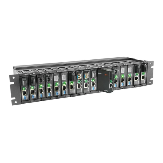
Chapter 2 Installation 2.1 Chassis Options The converter can be placed in any FMC series chassis, including the 17 slot CH17, 8 slot CH08 chassis. Chassis with built-in power are available with single AC (90-240VAC), single DC (18~75VDC). Dual AC, dual DC or AC plus DC combo for FMC-CH17 only. FMC-CH17 FMC-CH08 CH17-XX Chassis (XX=... -
Page 13: Chassis Electrical Installation
2.2 Chassis Electrical Installation With a built-in AC power chassis, AC power is supplied to the chassis through a standard IEC C14 3-prong receptacle, located on the rear of the chassis. Any national power cord with IEC C13 line plug may be used to connect AC power to the power module. With a built-in DC power chassis, DC -48V is connected to the terminal block located on the rear of the chassis, observing the proper polarity. -
Page 14: Installation Of Sfp Modules
2.4 Installation of SFP Modules CTC Union supplied SFP modules are of the Bale Clasp type. The bale clasp pluggable module has a bale clasp that secures the module into the SFP cage. 2.4.1 Inserting a Bale Clasp SFP Module into the Cage Step 1. -
Page 15: Chapter 3 Provisioning
Chapter 3 Provisioning 3.1 Web Login 3.1.1 Introduction In an effort to make Networking devices easier to configure, many devices can now be configured via a Web Page, which should be familiar to all Internet users. The web page is accessed by the Default IP Address of the device from a Web Browser such as Internet Explorer or Firefox in the following way: 10.1.1.1/ (Assuming the Default IP Address is 10.1.1.1 ) Before accessing this device by web browser, the IP address must be known or it must be reset or changed to be used on the desired... -
Page 16: Web Main Page
3.1.3 Web Main Page... -
Page 17: System Information, Network Information
3.1.4 System Information, Network Information The information displayed on this page gives specific device, network information, and port status for the local FMC-100M(S) and for any remote that is accessible via IEEE802.3ah OAM in-band management. -
Page 18: System Information, Dd Information
3.1.5 System Information, DD Information The DD or DDOM information is read from the MSA compliant SFP module and can be displayed via the web user interface. 3.1.6 Local Settings If you have reviewed section 3.1 of this chapter, then you will already be familiar with these settings and their actions. We will go through the settings here again, but not with as much detail. -
Page 19: Ip Configuration
3.1.6.1 IP Configuration Use this screen to set the TCP/IP configuration for the local unit. Note, that if you change the IP address you could lose remote management for this device. Remember to save settings under the “Tools” menu. 3.1.6.2 Password Setting Key in the current password and type in the new password twice, then click the “Apply”... -
Page 20: Converter Configuration
3.1.6.3 Converter Configuration All of these special functions are explained in Section 3.1.8 of this chapter. Select the proper radio buttons and the click the “Apply” button. Remember to save settings under the “Tools” menu. -
Page 21: Port Configuration
3.1.6.4 Port Configuration This screen is for the configuration of the electrical Ethernet port (TP) and the optical port (FX). The options include enabling or disabling the port, setting auto or forced Ethernet mode, enabling 802.3X (flow control), and setting ingress and egress rate limiting. Note that rate limiting has a granularity of 64K so the rate can be set from 64k to 100M in 64K steps. -
Page 22: Rmon Counters
3.1.6.6 RMON Counters The counters have an accumulation of received bytes for each port (UTP, Fiber and Management) and more detailed distribution of those packets... -
Page 23: Vlan Group Configuration
3.1.6.7 VLAN Group Configuration FMC-100M(S) supports up to 16 VLAN groups. By using the check boxes for each port, the access to different VIDs can be controlled. -
Page 24: Vlan Per Port Configuration
3.1.6.8 VLAN Per Port Configuration In FMC-100M(S) there are actually three different ports, the external copper and fiber ports, plus the internal CPU port. The VLAN Per Port Setting page deals with how frames exit (egress) the copper, fiber and CPU (management). These are the Frame Egress Type. The following operations may be performed to the outgoing frames: <1>: Replace Tag The switch will remove VLAN tags from packets then add new tags to... -
Page 25: Remote Settings
/ health and to improve fault isolation. OAM only works point-to-point over the fiber link. In addition to standard 802.3ah functions like loop back and dying gasp, FMC-100M(S) also implements OAM to provide complete provisioning of the remote fiber connected converter, without using Layer 3 IP protocol. -
Page 26: 802.3Ah Configuration
3.1.8.1 802.3ah Configuration To use the OAM functions, the 802.3ah Functions setting must be enabled. It is not enabled by default. The 802.3ah mode is used to configure an OAM pair. In a pair, one unit must be ‘active’, while the other must be ‘passive’. We typically place the remote converter (CPE) in ‘passive’... -
Page 27: Loop Back Test
3.1.8.2 Loop back Test The loop back test is a non-intrusive test which uses OAM packets and will not affect normal transmissions. The number of OAM frames used (the number of times the loop back is done) is set by the Send Packet Number. The default is 1 packet. The Packet Length (Not including CRC) controls the packet size of the OAM frames used for loop back testing. -
Page 28: 802.3Ah Status
3.1.8.3 802.3ah Status The Global Config fields display the state of OAM, if OAM is enabled. We can also see the MAC addresses of the local and remote units in the OAM manageable pair. The Flags Field list the results of individual events based on the results of OAM protocol data units (OAMPDUs). Lastly, when two OAM devices start negotiation, there is Discovery Information passed between them. - Page 29 Most information carried by OAMPDU is encoded using type-length-value (TLV) format. The first octet (or byte) of the OAMPDU indicates the type. This type is used to let the OAM client know how to decode the bytes containing the information. The next octet carries the length of the information.
-
Page 30: Tools
One of the most critical problems in an access network for carriers is differentiating between a simple power failure at the customer premise and an equipment or facility failure. Dying gasp provides this information by having a station indicate to the network that it is having a power failure. -
Page 31: System Reboot
3.1.9.1 System Reboot When the converter is rebooted, all counters and registers are cleared and the converter starts fresh. If OAM is enabled, the discovery process will start. After selecting the System Reboot menu item, a confirmation dialogue box will pop up. Click “OK” to reboot the converter or click “Cancel”... -
Page 32: Firmware Upgrade
3.1.9.3 Firmware Upgrade If bugs are discovered, if functions are added, or if factory default settings are changed, the firmware in the converter will require upgrading. The only method to do upgrade for this converter is through the local Web (HTTP) user interface. The firmware image is uploaded from the browser (Post), it is checked for integrity, the flash is erased and then the flash is written with the new image. -
Page 33: Logout
3.2.1 Factory Default. Apply power to FMC-100M(S) and allow 25-30 seconds to fully boot. Using a pencil or ball-point pen, press the 'DEFAULT' recessed push- button switch (located on the face plate) and hold for 6 seconds or more then release. DO NOT POWER OFF; Allow the unit to again fully reboot (about 25 seconds). -
Page 34: Led Observations
Fiber Port cage. Use a simplex patch cable (single fiber strand, LC to LC), route the SFP Tx back to the Rx optical connection. The FX LNK LED should light. For FMC-100M, use a simplex patch cable (single fiber strand, SC to SC, ST to ST or FC to FC), route the Tx back to the Rx optical connection. -
Page 35: Ping Test
With FMC-100M(S) reset to factory default, connect a PC and configure the PC to the 10.1.1.0 network (10.1.1.100 recommended). Use a PC to ping FMC-100M(S) at its factory default IP address of 10.1.1.1. With a direct connection to PC, there should be no time outs and ping latency should be less than 1 millisecond.
Need help?
Do you have a question about the FMC-100M and is the answer not in the manual?
Questions and answers