Table of Contents
Advertisement
Quick Links
Advertisement
Table of Contents

Related Manuals for CTC Union FMC-2000MS


Summary of Contents for CTC Union FMC-2000MS
- Page 1 USER MANUAL FMC-2000MS Gigabit Ethernet OAM/IP Media Converter...
- Page 3 This Manual supports the following models: FMC-2000MS : 1x100/1000Base-FX (SFP) + 100/1000Base-X (Adapter Type) FMC-2000MS : 1x100/1000Base-FX (SFP) + 100/1000Base-X (with Built-in AC or DC Power) 2022 CTC Union Technologies Co., LTD. All trademarks are the property of their respective owners.
- Page 4 CTC Union products are not designed, intended, or authorized for use in systems or applications intended to support or sustain life, or for any other application in which the failure of the product could create a situation where personal injury or death may occur. Should the Buyer purchase or use a CTC Union product...
-
Page 5: Table Of Contents
Table of Contents CHAPTER 1 INTRODUCTION ................................................8 1.1 W ........................................................ 8 ELCOME 1.2 P ....................................................8 RODUCT ESCRIPTION 1.3 P ....................................................9 RODUCT EATURES 1.4 S ....................................................... 10 PECIFICATIONS 1.5 P ........................................................11 ANEL 1.6 LED I ..................................................... 13 NDICATORS 1.7 F .................................................. - Page 6 3.2 W ....................................................36 ROVISIONING 3.2.1 Introduction ....................................................36 3.2.2 Web Login Page ..................................................36 3.2.3 Web Main Page ..................................................37 3.2.4 System ......................................................38 3.2.5 IP ......................................................... 39 3.2.6 SNTP ......................................................40 3.2.7 Time ......................................................40 3.2.8 Log ......................................................40 3.2.9 Auto Laser Shutdown ..................................................
- Page 7 3.3 T ....................................................58 ROUBLESHOOTING 3.3.1 Factory Default................................................... 58 3.3.2 LED Observations ..................................................58 3.3.2.1 Power On ........................................................... 58 3.3.2.2 UTP Link Test........................................................59 3.3.2.3 Fiber Link Test ........................................................59 3.3.3 Operation Checks ..................................................59 3.3.3.1 Converter Check ......................................................... 59 3.3.3.2 Ping Test ..........................................................
-
Page 8: Chapter 1 Introduction
Thank you for choosing FMC-2000MS Gigabit Ethernet OAM/IP Web Smart Media Converter. Throughout this document, the Web Smart Media Converter will be referred to as FMC-2000MS or in an abbreviated form as just 2000MS. If you would like to skip right to the installation of the converter, proceed to Chapter 2. -
Page 9: Product Features
▪ Supports NTP v3/4 client with manual Timezone setting FMC-2000MS SFP socket supports a wide range of standard SFP modules to address any network situation. Single-mode, Multi-mode, Multi-rate, Dual Rate (100M or 1G), Single fiber bi-directional, Coarse and Dense Wave Division Multiplexing... -
Page 10: Specifications
1.4 Specifications Model Spec. FMC-2000MS Item Optical Interface Connector SFP cage Data rate 100/1000Base-X (125Mbps/1.25GMbps optical rate) Dual Rate with supported SFP Duplex mode Full duplex on fiber Electrical Interface Connector RJ-45, shielded Data rate auto, 10Mbps (10Base), 100Mbps (100Base), or 1000Mbps (1000Base) -
Page 11: Panel
1.5 Panel Front Panel Figure 1. FMC-2000MS Front Panel SFP fiber slot LED indicators USB Console port RJ-45 LAN port Reset-to-default button... - Page 12 Rear Panel 18~60V 100~240V DC 18~60V DC 12V 100~240V Figure 4. Built-in Power Figure 5. Built-in Power Figure 2. Adapter Type Figure 3. Built-in Power (DC) Type (AC or DC) Type Rear Panel (AC) Type Rear Panel Rear Panel (metal) Rear Panel...
-
Page 13: Led Indicators
1.6 LED Indicators Color Status Definition Light if power is connected and active. Green Power is not connected. Flashing 1. S/W Upgrading or 2. Waiting for IP from DHCP server ON steadily Light when the fiber port has an optical link but no link activity. FX LNK Green Flashing... -
Page 14: Chapter 2 Installation
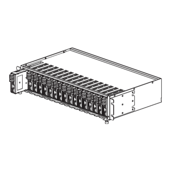
Chapter 2 Installation 2.1 Chassis Options The adapter-type 2000MS converters can be placed in any FMC series chassis, including the 17 slot CH17, 8 slot CH08 chassis. Chassis with built-in power are available with single AC (90-240VAC), single DC (18~60VDC). Dual AC, dual DC or AC plus DC combo for FMC-CH17 only. -
Page 15: Electrical Installation
2.2 Electrical Installation With a built-in AC power chassis, AC power is supplied to the chassis through a standard IEC C14 3-prong receptacle, located on the rear of the chassis. Any national power cord with IEC C13 line plug may be used to connect AC power to the power module. With a built-in DC power chassis, DC -48V is connected to the terminal block located on the rear of the chassis, observing the proper polarity. -
Page 16: Installation Of Sfp Modules
2.4 Installation of SFP Modules CTC Union supplied SFP modules are of the Bale Clasp type. The bale clasp pluggable module has a bale clasp that secures the module into the SFP cage. 2.4.1 Inserting a Bale Clasp SFP Module into the Cage Step 1. -
Page 17: Chapter 3 Provisioning
All FMC-2000MS converters have a USB Type-C™ connector which may be connected to a host computer. If your host computer has a USB Type-C™ port, use a USB Type-C™ to USB Type-C™ cable to connect the FMC-2000MS to the host. If the host has a regular USB Type-A™... -
Page 18: Terminal Operation
3.1.2 Terminal Operation PuTTY and TeraTerm Pro are two of the most popular, free, terminal emulation programs available from the Internet. In the examples here, the TeraTerm Pro program will be used, under Windows 10. TeraTerm Pro Setup Under the "Setup" pull-down menu, choose the "Serial port.." menu item. Remembering the COM port number from the Device Manager, set the port number (COM7 in this example). -
Page 19: Login
3.1.3 Login FMC-2000MS Login Screen The default username is 'admin' with no password. Note: If password is lost, return device to factory default (see page 13, Section 1.7) -
Page 20: Main Menu
3.1.4 Main Menu **************************************** CTC UNION TECHNOLOGIES CO.,LTD FMC-2000MS **************************************** [1.000-1.002-0.000-0.000][Standalone] <1> System <2> Automatic Laser Shutdown <3> Ports <4> Link OAM <5> SNMP <6> MAC Table <7> VLAN <8> QoS <9> Diagnostics <A> Maintenance <P> Password Change <S> Save startup-config [ESC] Logout <1>... -
Page 21: System
3.1.5 System < System > <1> Information <2> IP <3> SNTP <4> Time Zone <5> Log <6> Work in [Switch] Mode ** In converter mode, the CPU port will be disconnected. [ESC] Go to previous menu. Please select an item. <1>... - Page 22 LINK-UP: Local FIBER Port, changed state to up 2022-02-11T15:08:11+08:00 REMOTE: FMC-2000MS UP <6> Work in [Switch] Mode: The normal mode of operation for this device is "Switch" mode. The store and forward mechanism between the LAN and FIBER ports allows for different speeds and duplexes between the two, for example 10Base or 100Base on the LAN while the FIBER speed is 1000Base.
-
Page 23: Automatic Laser Shutdown
3.1.6 Automatic Laser Shutdown Automatic Laser Shutdown (ALS) is a technique used to automatically shut down the output power of the transceiver in case of fiber breakage, according to ITU-T G.664. If a fiber is cut, the receiver will detect a Loss Of Signal (LOS). The ALS agent will turn off the transmit laser. The receiver at the far end will then detect an LOS and its ALS agent will turn off its transmit laser. - Page 24 <2> Fiber Flow Control: Enables or disables the 802.3x Ethernet flow control for the port. ---------------------------------------------------------- <0> Disable <1> Enable <ESC> Exit <3> LAN Speed: Sets up the LAN port speed and duplex or sets in auto-negotiation mode. (hdx= half duplex, fdx= full duplex) ---------------------------------------------------------------------- <0>...
- Page 25 <8> Detailed Statistics: Choose the port, LAN (1) or FIBER (2) and use the "greater than, less than" (>, <) keys to show next or previous pages of statistics. { Port > LAN Statistics } RX Packets: 39494 TX Packets: RX Octets: 6166496 TX Octets:...
-
Page 26: Link Oam
This media converter supports standard IEEE802.3ah OAMPDU such as discovery, loopback and dying gasp. Additionally, organizational specific OAMPDU are used to create layer 2 in-band management between a local and a remote converter, either another FMC-2000MS or a legacy FMC-1000MS. - Page 27 <2> Port Statistics: List the OAM port statistics for LAN and Fiber ports. { Link-OAM > FIBER Statistics } Rx Loopback Control Tx Loopback Control Rx Link Fault PDUs Tx Link Fault PDUs Rx Dying Gasp Tx Dying Gasp Rx Critical Event PDUs [ Tx Critical Event PDUs [ [1] LAN [2] FIBER...
-
Page 28: Snmp
<4> Remote Device (FMC-2000MS): This menu item allows entering configuration of the remote OAM fiber connected converter. If the remote converter is not seen, make sure that OAM is enabled on both converters and make sure the local converter is in 'active' mode. The factory default has the converters in 'passive' mode. -
Page 29: Mac Table
3.1.10 MAC Table This device has features to modify the MAC table aging time as well as being able to create static MAC entries in the MAC table. { MAC Table } <1> Aging Time <2> MAC Table Configuration <3> MAC Address Table [ESC] Go to previous menu. -
Page 30: Vlan
<3> MAC Address Table: This device has a 1024 MAC table and all MACs may be displayed through this menu item. Once the table is full, a packet with a new MAC will pass unfiltered. A new MAC will not be added until an address has timed out and is removed from the table. Only then could a new MAC be added. - Page 31 <1> Configuration: Setup the VLAN configurations for the Fiber and the LAN port. { VLAN > Configuration } <0> Ethertype for Custom S-ports [88A8] { FIBER } <1> Port VLAN <2> Port Type [C-Port <3> Ingress Acceptance [Tagged and Untagged] <4>...
-
Page 32: Qos
3.1.12 QoS The Quality of Service (QoS), in this device, refers to the egress bandwidth control and the broadcast storm protection. { QoS } <1> Bandwidth Control <2> Storm Policing <1> Bandwidth Control: Provides egress rate limiting for both the LAN and Fiber ports. { QoS >... -
Page 33: Diagnostics
<2> Storm Policing: To prevent ARP, ICMP, broadcast, and multicast packets impacting the performance of CPU, this device can drop those ARP, ICMP, broadcast and multicast frames in a specific period. This storm prevention may be enabled separately for ARP, ICMP, multicast and broadcast packets. - Page 34 <1> Upgrade via TFTP <2> Upgrade via X-Modem <3> Swap <1> Upgrade via TFTP: TFTP upgrade method requires a TFTP server, accessible on the network by the FMC-2000MS, and with an image file on the TFTP server. ---------------------------------------------------------- Syntax : <host> <file_name>, Example: 10.1.1.1 update.mfi <2>...
- Page 35 <5> Configuration: The final member of the Maintenance group is the configuration management. { Maintenance > Configuration } <1> Save startup-config <2> Download <3> Upload <1> Save startup-config: This device, when cold booted, will copy the "startup-config" into memory as the "running-config" and then run all operations from this running configuration in memory.
-
Page 36: Web Provisioning
3.2 Web Provisioning 3.2.1 Introduction To make Networking devices easier to configure, many devices can now be configured via a Web GUI, which should be familiar to all Internet users. The web page is accessed by the Default IP Address of the device from a Web Browser such as Chrome, Internet Explorer or Firefox in the following way: http://10.1.1.1/ (Assuming the Default IP Address is 10.1.1.1) Before accessing this device by web browser, the IP address must be known or it must be reset or changed to be used on the desired... -
Page 37: Web Main Page
3.2.3 Web Main Page Logout The first page will present the user with the Function Menu in the Left-hand frame and the Ports State Overview in the main frame. -
Page 38: System
3.2.4 System Configuration These three fields provide the information that will be reported by SNMP standard MIB2. Information The information displayed here gives specific System fields, the hardware MAC address of this device, the current system time (as set from a Network Time Server), the system "uptime"... - Page 39 3.2.5 IP Configuration This device supports setting a management VID as well as both static or dynamic IPv4 and IPv6 IP addresses, subnet mask and default gateway. When DHCP is enabled, this device will look for a DHCP server and dynamically receive an IP address from the DHCP server's available pool of IP addresses.
-
Page 40: Sntp
3.2.6 SNTP Enables the NTP client function with a primary and backup Network Time Protocol Server. 3.2.7 Time Configures the Time Zone by entering the hours and minutes offset from UTC (Universal Time Coordinates). 3.2.8 Log Information... -
Page 41: Auto Laser Shutdown
Detailed Browse the log ID by ID using First (|<<), Previous (<<), Next (>>) and Last (>>|) buttons. 3.2.9 Auto Laser Shutdown Automatic Laser Shutdown (ALS) is a technique used to automatically shut down the output power of the transceiver in case of fiber breakage, according to ITU-T G.664. -
Page 42: Ports
3.2.10 Ports Configuration Set the configured link speed/duplex or Auto for the LAN and Fiber port. Enable or disable flow control (802.3x) by checkbox. Use pull-downs to enable/disable LLPT and jumbo frames. State Overview This is a graphical view of the real-time state of the ports and the LEDs. The orange FX SPD and LAN SPD indicate gigabit links. - Page 43 For an SFP module which supports DDOM, all details of the SFP will be shown. Note that Wave Length(2) is a special field only filled when a CTC Union branded BiDi SFP is inserted. The Wave Length will indicate the Tx lambda while Wave Length(2) indicates the Rx lambda.
-
Page 44: Link Oam
This media converter supports standard IEEE802.3ah OAMPDU such as discovery, loopback and dying gasp. Additionally, organizational specific OAMPDU are used to create layer 2 in-band management between a local and a remote converter, either another FMC-2000MS or a legacy FMC-1000MS. - Page 45 Port Status Displays the status of Fiber or LAN port.
-
Page 46: Remote Device
3.2.12 Remote Device This web page allows entering configuration of the remote OAM connected converter. If the fiber connected remote converter is not seen, make sure that OAM is enabled on both converters and make sure the local converter is in 'active' mode. The factory default has the converters in 'passive' mode. -
Page 47: Snmp
SNMP or Simple Networking Management Protocol is a standard protocol for centralized management. Up to 4 management IPs can be configured in the FMC-2000MS, their community string defined, and their access defined as read-only or read-write. A read-only manager is only able to perform 'get' commands. -
Page 48: Security -User Password
3.2.14 Security -User Password Create a password if none exists or change the password here, then click the 'Save' button. 3.2.15 MAC Table Configuration Enable or disable MAC learning and set the aging time here. Supports 56 ~ 30037 seconds, in multiples of 7. Static MAC addresses (up to 16) may be added through the "Add New Static Entry"... -
Page 49: Mac Table Display
3.2.16 MAC Table Display Select 'Static', 'Dynamic', or both... -
Page 50: Vlan Configuration
3.2.17 VLAN Configuration S-Port default is 0x88A8, but may be user defined A virtual LAN (VLAN) is any broadcast domain that is partitioned and isolated in a computer network at the data link layer (OSI layer 2). This device supports C-Port (802.1Q, with EtherType 0x8100) and S-Port (802.1ad or QinQ, with EtherType 0x88A8 or user defined) configurations, with both ingress and egress filtering and allowed VLAN lists, with up to 16 individual VLAN ID groups. -
Page 51: Vlan Membership And Port Status
3.2.18 VLAN Membership and Port Status This is a display only of all VIDs and their port membership. This is a display only overview of VLAN port status. 3.2.19 QoS Bandwidth Control The outgoing (egress) rate limits, in Kbps, can be set on the Fiber and/or LAN ports. The rate is set with a granularity of 64Kbps, from 1 (64Kbps) to 16000 (1024000Kbps). -
Page 52: Storm Policing
3.2.20 Storm Policing To prevent ARP, ICMP, broadcast, and multicast packets impacting the performance of CPU, this device can drop those ARP, ICMP, broadcast and multicast frames in a specific period. This storm prevention may be enabled separately for ARP, ICMP, broadcast and multicast packets. -
Page 53: Maintenance
3.2.22 Maintenance Nine menu items under this item provide restart, factory default, software upgrade, and configuration management. 3.2.22.1 Restart Device Use this option to perform a cold reboot. Confirmation is required. The device will block traffic for about 15 seconds until fully booted. Configuration is loaded from the saved startup-config. -
Page 54: Auto Provisioning
3.2.22.3 Auto Provisioning This device supports auto provisioning using DHCP Option 66, 67 and 254. Setup of DHCP server is beyond the scope of this user manual. 3.2.22.4 Auto Provision Status Display the results of auto-provisioning 3.2.22.5 Software Upload Use this item to perform software upgrade. Click 'Browse' to locate the upgrade image file, then click 'Upload' to start the upgrade process. -
Page 55: Software Image Select
3.2.22.6 Software Image Select The device can swap the "Active" image with the "Alternate" firmware image. Whenever the software is upgraded, whether by Web posting, TFTP or serial X-Modem, the "Active" image will become the new "Alternate" image, while the new software will become the new "Active" image. Swapping allows falling back to the previous software version. -
Page 56: Configuration Download
This device supports configuration backup by downloading (a pure text format file) either the startup or running configuration to a local file through the browser from HTTP. Partial example of the contents of downloaded file. hostname FMC-2000MS.250 username admin password encrypted ys7FoSrVZvE4wBRihiyUdQ==24 sntp sntp server 1 ip-address 192.168.0.254... -
Page 57: Configuration Upload
3.2.23 Logout Logging out will ensure that the management session with FMC-2000MS is terminated. This is especially important if you are using a public computer to manage the device. Once logged out, a password must be entered to access FMC-2000MS again. -
Page 58: Troubleshooting
If all LEDs immediately light and never turn off, or if no LED ever lights, then the card is possibly defective. Be sure to double check power source and try either another FMC-2000MS in the same chassis or try the card in a different chassis or with a different power adapter. -
Page 59: Utp Link Test
3.3.3.1 Converter Check A very easy way to ensure a pair of FMC-2000MS is passing traffic, is to place them between two PCs. Connect PC1 to LAN of one converter and PC2 to LAN of the other converter. When the two PCs can ping each other, it indicates FMC-2000MS pair is operational. -
Page 60: Web Access Test
With FMC-2000MS reset to factory default, connect a PC and configure the PC to the 10.1.1.0 network (10.1.1.100 recommended). Use a PC to connect to FMC-2000MS at its factory default IP address of 10.1.1.1 using a web browser (Internet Explorer, Firefox, Chrome, etc.). The local web page login page should display. -
Page 61: Appendix
Appendix MIB Description Label Access Description Indicates DHCPv4 IP address is ctcAutoProvisioningStatusGlobalsDHCPv4Bound .1.3.6.1.4.1.4756.189.20.145.1.3.1.3 ReadOnly bound or not. Indicates the configuration is up to ctcAutoProvisioningStatusGlobalsConfigurationUpToDate .1.3.6.1.4.1.4756.189.20.145.1.3.1.2 ReadOnly date or not. Indicates the software is up to ctcAutoProvisioningStatusGlobalsSoftwareUpToDate .1.3.6.1.4.1.4756.189.20.145.1.3.1.1 ReadOnly date or not. Configure the DHCP option 60 vendor class identifier. - Page 62 The location of configuration files to upload or download. It is a specific character string that constitutes a reference to a resource. Syntax: <protocol>://<host>/<file_name> For example ctcIcfgControlCopyConfigConfigFileUrl .1.3.6.1.4.1.4756.189.20.101.1.4.2.3 ReadWrite tftp://10.10.10.10/config.txt. A valid file name is a text string drawn from alphabet (A-Za-z) digits (0-9) dot (.) hyphen (-) under score(_).
- Page 63 Indicates the last uploading running-config filename the configuration file can upload from ctcIcfgStatusConfigUploadFilename .1.3.6.1.4.1.4756.189.20.101.1.3.4.1 ReadOnly TFTP or HTTP by manually or upload from TFTP HTTP or FTP by Auto-provision. The status indicates the status of current copy operation. none(0) means no copy operation. success(1) means copy operation is successful.
- Page 64 The number of received and ctcLinkOAMStatisticsCriticalEvent .1.3.6.1.4.1.4756.189.20.79.10.1.60 ReadOnly transmitted OAM Critical Event packets. The number of received and ctcLinkOAMStatisticsDyingGasp .1.3.6.1.4.1.4756.189.20.79.10.1.50 ReadOnly transmitted OAM Dying Gasp packets. The number of received and ctcLinkOAMStatisticsLinkFault .1.3.6.1.4.1.4756.189.20.79.10.1.40 ReadOnly transmitted OAM Link Fault packets. The number of received and ctcLinkOAMStatisticsLoopback .1.3.6.1.4.1.4756.189.20.79.10.1.30 ReadOnly...
- Page 65 The location of image to upload. It is a specific character string that constitutes a reference to a resource. Syntax: <protocol>://<host>/<file_name> For example tftp://10.10.10.10/new_image.mfi. ctcFirmwareControlImageUploadUrl .1.3.6.1.4.1.4756.189.20.28.1.4.2.3 ReadWrite A valid file name is a text string drawn from alphabet (A-Za-z) digits (0-9) dot (.) hyphen (-) under score(_).
- Page 66 errInvalidImage(7) means upload operation is failed due to invalid image. errWriteFlash(8) means upload operation is failed due to failed writing flash. errSameImageExisted(9) means upload operation is failed because the upload image is the same as the one in flash. errUnknownImage(10) means upload operation is failed because the type of upload image is unknown.
- Page 67 The built date when the image is ctcFirmwareStatusImageBuiltDate .1.3.6.1.4.1.4756.189.20.28.1.3.1.1.5 ReadOnly built. ctcFirmwareStatusImageVersion .1.3.6.1.4.1.4756.189.20.28.1.3.1.1.4 ReadOnly Image version. Image type of the status. bootloader(0) is for boot loader. activeFirmware(1) is for active ctcFirmwareStatusImageType .1.3.6.1.4.1.4756.189.20.28.1.3.1.1.2 ReadOnly (primary) firmware. alternativeFirmware(2) is for alternative (backup) firmware. Type of reboot.
- Page 68 ReadWrite Storm control threshold storm ctcQosConfigGlobalsStormPolicersMulticastThreshold .1.3.6.1.4.1.4756.189.20.14.1.2.1.1.6 counter clear period is 100ms ReadWrite If true the storm policer is ctcQosConfigGlobalsStormPolicersMulticastEnable .1.3.6.1.4.1.4756.189.20.14.1.2.1.1.5 enabled. ReadWrite Storm control threshold storm ctcQosConfigGlobalsStormPolicersICMPThreshold .1.3.6.1.4.1.4756.189.20.14.1.2.1.1.4 counter clear period is 100ms ReadWrite If true the storm policer is ctcQosConfigGlobalsStormPolicersICMPEnable .1.3.6.1.4.1.4756.189.20.14.1.2.1.1.3 enabled.
- Page 69 The number of transmitted frames ctcPortStatisticsTx128to255Pkts .1.3.6.1.4.1.4756.189.20.11.1.5.1.1.30 ReadOnly with size within 128 to 255 bytes. The number of transmitted frames ctcPortStatisticsTx65to127Pkts .1.3.6.1.4.1.4756.189.20.11.1.5.1.1.29 ReadOnly with size within 65 to 127 bytes. The number of 64 bytes frames ctcPortStatisticsTx64Pkts .1.3.6.1.4.1.4756.189.20.11.1.5.1.1.28 ReadOnly transmitted. The number of pause frames ctcPortStatisticsTxPauseFrames .1.3.6.1.4.1.4756.189.20.11.1.5.1.1.27...
- Page 70 The number of received frames ctcPortStatisticsRx512to1023Pkts .1.3.6.1.4.1.4756.189.20.11.1.5.1.1.12 ReadOnly with size within 512 to 1023 bytes. The number of received frames ctcPortStatisticsRx256to511Pkts .1.3.6.1.4.1.4756.189.20.11.1.5.1.1.11 ReadOnly with size within 256 to 511 bytes. The number of received frames ctcPortStatisticsRx128to255Pkts .1.3.6.1.4.1.4756.189.20.11.1.5.1.1.10 ReadOnly with size within 128 to 255 bytes. The number of received frames ctcPortStatisticsRx65to127Pkts .1.3.6.1.4.1.4756.189.20.11.1.5.1.1.9...
- Page 71 The period is Tx laser power turn OFF. The allowed range is 10 to 50 ctcPortAlsPowerOnPeriod .1.3.6.1.4.1.4756.189.20.11.1.2.2.1.3 ReadWrite in tenths of seconds default period is 30 in tenths of seconds (3 second). Enable/Disable the laser power of ctcPortAlsEnabled .1.3.6.1.4.1.4756.189.20.11.1.2.2.1.2 ReadWrite transceiver module shutdown automatically.
- Page 73 This page is intentionally left blank. Version Descriptions Date release 2022/03/02 Update – metal case, remove ingress QOS, add USB TM 2022/03/29...
Need help?
Do you have a question about the FMC-2000MS and is the answer not in the manual?
Questions and answers