Table of Contents
Advertisement
micro SD card real time data logger
CAT III 1000V, true rms, L/C
MULTIMETER
Model : DM-9962SD
OPERATION MANUAL
OPERATION MANUAL
Your purchase of this
MULTIMETER marks a
step forward for you
into the field of
precision measurement.
Although this
MULTIMETER is a
complex and delicate
instrument, its durable
structure will allow
many years of use if
proper operating
techniques are
developed. Please read
the following
instructions carefully
and always keep this
manual within easy
reach.
Advertisement
Table of Contents

Related Manuals for Lutron Electronics DM-9962SD


Summary of Contents for Lutron Electronics DM-9962SD
- Page 1 SD card real time data logger CAT III 1000V, true rms, L/C MULTIMETER Model : DM-9962SD Your purchase of this MULTIMETER marks a step forward for you into the field of precision measurement. Although this MULTIMETER is a complex and delicate...
- Page 2 Caution Symbol Caution : * Risk of electric shock ! Caution : * Do not apply the overload voltage, current to the input terminal ! * Remove test leads before open the battery cover ! * Cleaning - Only use the dry cloth to clean the plastic case ! Environment Conditions * Installation Categories III-1000V.
-
Page 3: Table Of Contents
TABLE OF CONTENTS FEATURES..................1 SPECIFICATIONS................2 2-1 General Specifications..............2 2-2 Electrical Specifications.............. 3 FRONT PANEL DESCRIPTION............6 PRECAUTIONS & PREPARATIONS FOR MEASUREMENT................MEASURING PROCEDURE............8 5-1 Symbols & Units of Display ............8 5-2 DC voltage, AC voltage true rms Measurement ........5-3 Resistance Measurement............ - Page 4 Saving data from the Micro SD card to the computer......... ADVANCED SETTING..............8-1 Micro SD memory card Format............. 8-2 Set sampling time..............24 8-3 Set Auto power OFF management............... 8-4 Set beeper sound ON/OFF..............8-5 Set Decimal point of Micro SD card setting..........8-6 Set clock time(Year/Month/Date,Hour/Minute/Second)....
-
Page 5: Features
1. FEATURES Real time Datalogger, save the into the micro SD memory card and can be downloaded to the Excel, extra software is no need. Real time Datalogger, it Built-in Clock (year/month/date/ hour/minute/second ), sampling time set from 2 seconds to 3600 seconds. -
Page 6: Specifications
2. SPECIFICATIONS 2-1 General Specifications Display 60 mm x 39 mm large LCD display Measurement DCV, ACV, DCA, ACA, Resistance,Diode, Continuity beeper,Capacitance,Inductance, Frequency, Temperature. Datalogger 2 seconds to 3600 seconds Auto Sampling Time Setting range Manual Push the data logger button once will save data one time. -
Page 7: Electrical Specifications
Dimension 190 x 88 x 40 mm ( 7.5 x 3.5 x 1.6 inch ). Weight 387 g/0.85 LB ( w.o battery ). Accessories Red and Black Test Leads Included ( CAT III 1KV Test Leads )...... 1 Set 600 mA Spare Fuse........ 1 PC Instruction Manual........ - Page 8 DC Current, AC Current ( True RMS ) DC Current, AC Current ( True RMS ) DC Current, AC Current ( True RMS ) DC Current, AC Current ( True RMS ) Range 10 A/6 A/600 mA/60 mA/6000 uA/600 uA Resolution 0.01 A/0.001 A/0.1 mA/0.01 mA/1 uA/0.1 uA Accuracy...
- Page 9 Frequency Frequency Frequency Frequency Range 600 Hz/6 KHz/60 KHz/600 KHz/6 MHz/20 MHz Resolution 0.1 Hz/0.001 KHz/0.01 KHz/0.1 KHz/0.001 MHz/0.01 MHz Accuracy ±( 0.5% + 2d ) Sensitivity Min. 1 V rms, Max. 5 V rms. OHMS Range 600 /6 K /60 K /600 K /6 M /60 M Resolution 0.1 /0.001 K /0.01 K /0.1 K /0.001 M /0.01 M Accuracy...
-
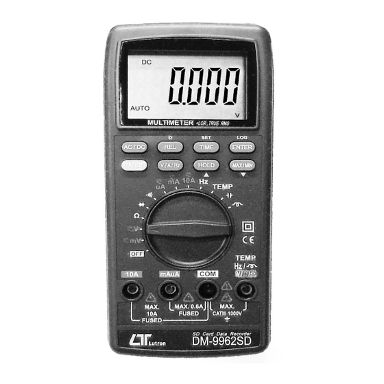
Page 10: Front Panel Description
3. FRONT PANEL DESCRIPTION Fig. 1 3-1 Display 3-10 Function rotary switch 3-2 MAX/MIN ( ) button 3-11 Temp./ohm/V/Cap. input terminal 3-3 TIME (SET) button 3-12 COM input terminal 3-4 REL(Backlight) button 3-13 mA/uA input terminal 3-14 10A input terminal 3-5 HOLD ( ) button 3-6 RANGE button... -
Page 11: Precautions & Preparations For Measurement
4. PRECAUTIONS & PREPARATIONS FOR MEASUREMENT 1) Ensure that the DC 9 V ( 006P, MIN1604 ) batteries are connected with the right polarity and placed in the battery compartment correctly. 2) Place the Red & Black Test Leads into the proper input terminal before making measurement. -
Page 12: Measuring Procedure
5. MEASURING PROCEDURE 5-1 Symbols & units of display Symbols Descriptions Units AUTO Appears when selecting " Automatic range " mode. Appears when selecting " Manual range " mode. MANU Appears when selecting DC mode. ( DC voltage or DC current ) Appears when selecting AC mode. -
Page 13: Dc Voltage, Ac Voltage True Rms Measurement
5-2 DC Voltage, AC voltage true rms Measurement 1) Connect BLACK test lead into " COM " terminal ( 3-12, Fig. 1 ). 2) Connect RED test lead into " V " terminal ( 3-11, Fig. 1 ). 3) Select the " Function rotary switch " ( 3-10, Fig. 1 ) to the "... -
Page 14: Dc Current, Ac Current True Rms Measurement
5) Under the operation of " auto range " mode, push the " Range button " ( 3-6 Fig. 1 ) will execute the " Manual Range " mode and hold the range, the LCD will show the " MANU " marker. Under the manual range operation, push the "... -
Page 15: Continuity Check
Under the operation of " auto range " mode, push the " Range button " ( 3-6 Fig. 1 ) once will execute the " Manual Range " mode and hold the range, the LCD will show the " MANU " marker. Under the manual range operation, push the "... - Page 16 Fig. 2 Fig.2 b. When connected as shown in Fig. 3, a reverse check on the diode is made. If the diode under test is good, "––––" will be displayed. If the diode under test is defective, " 0.000 " or other numbers will be displayed. Proper diode testing should include both steps a.
-
Page 17: Capacitance Measurement
5-7 Capacitance Measurement Select the " Function rotary switch " ( 3-10, Fig. 1 ) to the " " position. Connect the tested capacitor to " Input terminals " directly. * If the measured capacity existing the polarity, then should connect the " + " polarity of the measured capacitor to the "... -
Page 18: L/C Calibration
5-9 L/C Calibration In order to improve the accuracy of a high / low impedance, Recommend doing open / short calibration Before measurement. Open / short calibration procedure: Simultaneously push " AC / DC " and " REL " button more to start open / short calibration,The display will show "OPEn", than 2 seconds, then push "ENTER"... -
Page 19: Temperature Measurement
5-11 Temperature Measurement Plug in the optional " Type K Temperature probe, TP-11 " into the input terminals, " TEMP input terminal " ( 3-11, Fig. 1 ) and the " COM input terminal " ( 3-12, Fig. 1 ) Select the "... -
Page 20: Max/Min. Value Record
5-15 Max and Min. value record Application : To record the maximum and the minimum reading value during the measurement. Push the " MAX/MIN button " ( 3-2, Fig. 1 ) at once , the display will show the " REC " markers Start recording meter the "... - Page 21 Each digit indicates the following status : Start Word (0X02) When send the upper display data = 1 D12, D11 Annunciator for Display DC mV = 18 AC mV = 49 uH = 68 DC V = 34 AC V = 50 mH = 41 DC uA = 35 AC uA = 51...
-
Page 22: Datalogger
6. DATALOGGER 6. DATALOGGER 6. DATALOGGER 6. DATALOGGER 6-1 Preparation before execute datalogger function 6-1 Preparation before execute datalogger function 6-1 Preparation before execute datalogger function 6-1 Preparation before execute datalogger function a. Insert the micro SD card Prepare a " micro SD memory card "( 4 GB to 32 GB, optional ) Open the Micro SD card cover(3-18, Fig. -
Page 23: Manual Datalogger
Remark : How to set the sampling time, refer to Chapter 8-2 , page 24 . How to set the beeper sound is enable, refer to Chapter 8- 4, page 25 . b. Pause the datalogger During execute the Datalogger function, if press the "... -
Page 24: To Check The Time And Sampling Time Information
Remark : During execute the Manual Datalogger, it can use the " Button " ( 3-5, Fig. 1) or " Button " ( 3-2, Fig. 1 ) to set the measuring position ( 1 to 99, for example room 1 to room 99 ) to identify the measurement location , the Display will show Px ( x = 1 to 99 ). -
Page 25: Saving Data From The Micro Sd Card To The Computer
Under the folder DMA01\, if the total files more than 99 files, will generate anew route, such as DMA02\ ..The file's route structure : DMA01\ DMA01001.XLS DMA01002.XLS ..... DMA01099.XLS DMA02\ DMA02001.XLS DMA02002.XLS ..... DMA02099.XLS DMAXX\ .......... Remark : XX : Max. - Page 26 EXCEL data screen ( for example ) EXCEL graphic screen ( for example, graphic )
-
Page 27: Advanced Setting
8. ADVANCED SETTING Under do not execute the Datalogger function, press the " SET Button " ( 3-3, Fig. 1 ) continuously at least two seconds will enter the " Advanced Setting " mode. then press the " SET Button " ( 3-3, Fig. 1 ) once a while in sequence to select the six main function, the display will show : Sd F.... -
Page 28: Set Sampling Time
2) If select the upper to " YES ", press the " Enter Button " ( 3-8, Fig. 1 ) once again, the Display will show text " Ent " to confirm again, if make sure to do the Micro SD memory card format, then press " Enter Button " once will format the Micro SD memory clear all the existing data that already saving into the Micro SD card. -
Page 29: Set Beeper Sound On/Off
8-4 Set beeper sound ON/OFF When the display show " bEEP " Use the " ▲ Button " ( 3-5, Fig. 1 ) or " ▼ Button " ( 3-2, Fig. 1 ) to select the upper text to " YES " or "... -
Page 30: Set Clock Time(Year/Month/Date,Hour/Minute/Second)
After select the upper text to " USA " or " Euro ", press the " Enter Button " ( 3-8, Fig. 1 ) will save the setting function with default. 8-6 Set clock time ( Year/Month/Date,Hour/Minute/ Second ) When the upper display show " dAtE " Use the "... -
Page 31: Maintenance
9. MAINTENANCE 9. MAINTENANCE 9. MAINTENANCE 9. MAINTENANCE 9-1 Battery replacement 9-1 Battery replacement 9-1 Battery replacement 9-1 Battery replacement Remove test leads before Remove test leads before Remove test leads before Remove test leads before Caution : Caution : Caution : Caution : opening the battery cover ! -
Page 32: Replacement Of Fuse
9-3 Replacement of Fuse Caution : When make the replacement, should change the right spec fuse. a. Fuse A - Rating :600 mA, Size : 5 mm dia. x 20 mm To be protected the circuit from overload current at "... -
Page 33: Optional Accessories & Adapters
10. OPTIONAL ACCESSORIES & ADAPTERS Memory card micro SD memory card ( 8 GB ) RS232 cable * Computer interface cable. UPCB-06 * Used to connect the meter to the computer ( COM port ). USB cable * Computer interface cable. USB-11 * Used to connect the meter to the computer ( USB port ). -
Page 34: The Address Of After Service Center
11. THE ADDRESS OF AFTER SERVICE CENTER 180525-DM-9962SD...
Need help?
Do you have a question about the DM-9962SD and is the answer not in the manual?
Questions and answers