Advertisement
100 Hz 120 Hz 1 KHz 10 KHz 100 KHz, Professional
╱
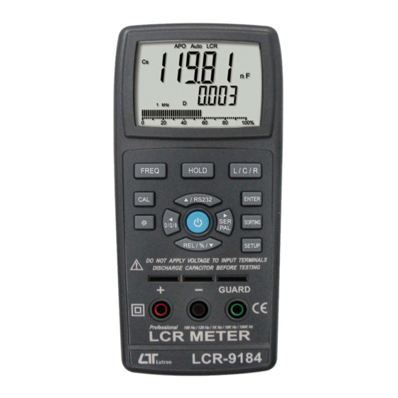
LCR METER
Model : LCR-9184
OPERATION MANUAL
╱
╱
╱
Your purchase of this LCR
METER
marks
forward for you into the
f i e l d
o f
measurement.
this
LCR
METER
complex
and
instrument,
structure will allow many
years of use if proper
operating techniques are
developed.
Please
the following instructions
carefully and always keep
this manual within easy
reach.
a
step
p r e c i s i o n
Although
is
a
delicate
its
durable
read
Advertisement

Related Manuals for Lutron Electronics LCR-9184


Summary of Contents for Lutron Electronics LCR-9184
- Page 1 100 Hz 120 Hz 1 KHz 10 KHz 100 KHz, Professional ╱ ╱ ╱ ╱ LCR METER Model : LCR-9184 Your purchase of this LCR METER marks step forward for you into the f i e l d p r e c i s i o n measurement.
-
Page 2: Table Of Contents
TABLE OF CONTENTS 1. FEATURES..............1 2. SPECIFICATIONS............1 2-1 General Specifications..........1 2-2 Electrical Specifications..........3 3. FRONT PANEL DESCRIPTION........6 3-1 Display..............6 3-2 Frequency Button..........6 3-3 Hold Button............6 3-4 L/C/R Button............6 3-5 CAL Button............6 Button, RS232 Button........▲ 3-7 < Button, D/Q/θ Button........6 3-8 REL/%/ Button........... -
Page 3: Features
1. FEATURES * 19,999/1,999 counts dual LCD display. * AutoLCR smart check and measurement. * Serial/Parallel modes are selectable. * Ls/Lp/Cs/Cp with D/Q/θ /ESR parameters. * Support DCR mode 1.00 Ω to 200.0 MΩ . * Five different test frequency are available : 100 Hz/120 Hz/1 KHz/10 KHz/100 KHz. - Page 4 θ ± 90° measurement Sorting ± 0.25%, ± 0.5%, ± 1%, ± 2%, ± 5% tolerance ± 10%, ± 20%, +80% -20% mode Calibration Open/Short calibration Data Hold Freeze the display reading Data output RS232/USB PC computer interface Power off Auto shut off saves battery life or manual off by push button Operating...
-
Page 5: Electrical Specifications
2-2 Electrical Specifications (23± 5 ℃ Resistance ( DCR ) Range Accuracy Remark 20 Ω After calibration ± ( 0.5% + 5d ) 200 Ω ± ( 0.5% + 5d ) 2 KΩ ± ( 0.5% + 5d ) 20 KΩ ±... - Page 6 Remark : * If the impedance is larger than 10 KΩ , Rp is shown on the display. * If the impedance is less than 10 KΩ , Rs is shown on the display. * If intend to obtain the accurate value, please test the component into the "...
- Page 7 Remark : * If the impedance is larger than 10 KΩ , Cp is shown on the display. * If the impedance is less than 10 KΩ , Cs is shown on the display. * If intend to obtain the accurate value, please test the component into the "...
-
Page 8: Front Panel Description
3. FRONT PANEL DESCRIPTION 3-1 Display 3-2 Frequency Button 3-3 Hold Button 3-4 L/C/R Button 3-5 CAL Button Button, RS232 Button ▲ 3-7 < Button, D/Q/θ Button 3-8 REL/%/ Button ▼ 3-9 > Button, SER/PAL Button 3-10 Power Button 3-11 Input terminals ( pin terminals ) 3-12 Input terminals ( banana terminals ) 3-13 DC 9V Power Adapter Input Socket 3-14 RS-232/USB Output Terminal... -
Page 9: Measuring Procedure
4. MEASURING PROCEDURE 4-1 Measuring procedure 1)Power on by pressing the " power on/off key ", the all segments of LCD will be ON for 2 seconds﹒ 2)The default mode is AUTO LCR smart mode and the default test frequency is 1 KHz. 3)In order to extend the battery life﹐it is recommended to use the external power supply and the APO setting ( Auto power off setting ).﹒When all function button do... -
Page 10: Data Hold
The phase angel ( θ ) or equivalent resistance ( ESR ) can also be shown by pushing the PARAMETER ( D/Q/θ ) keypad to choose D/Q/θ /ESR﹒When Auto-R(ACR mode) or DCR mode is selected﹐the secondary parameter is omitted﹒ Note 1 : When Auto LCR mode is active﹐the secondary parameter will show the equivalent resistance in parallel mode ( Rp ) to replace the D factor if... -
Page 11: The Select Of Test Frequency
4-4 The select of test frequency When FREQ key is pushed, the test frequency will be changed sequentially. There are five different test frequencies ( 100Hz/120Hz/1KHz/10KHz/100KHz ) can be selected﹒The LCR impedance scale range are depended on the test frequency, See the specifications. 4-5 REL /% The REL /% mode help the user to make a relative value of the component . -
Page 12: Calibration
The tolerance range setting selection : ± 0.25% ± 0.5% ± 1% ± 2% ± 5% → → → → ± 10% ± 20% +80% -20% → → → The default tolerance is ± 1%﹒ * Press Sorting button once will exit this function. 4-7 Calibration In order to improve the accuracy for high/low impedance, it is recommended to do OPEN/SHORT... -
Page 13: Power Supply From Dc Adapter
" batt " and the power will be shut down. 7. OPTIONAL ACCESSORIES SMD TESTER Model : SMDA-22 * Optional SMD tester for LCR-9184, LCR-9183. * Useful tool for SMD components ( Resistor, Capacitor,Inductor ) LCR value measurement. - Page 14 SMD TEST CLIP Model : SMDC-21 * Optional SMD test clip for LCR-9184,LCR-9183. * Useful test clip for SMD components ( Resistor, Capacitor,Inductor ) LCR value measurement. 1012-LCR9184...
Need help?
Do you have a question about the LCR-9184 and is the answer not in the manual?
Questions and answers