Table of Contents
Advertisement
Advertisement
Table of Contents

Subscribe to Our Youtube Channel
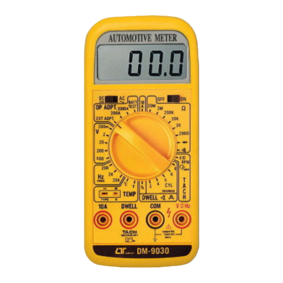
Summary of Contents for Lutron Electronics DM-9030
-
Page 2: Table Of Contents
TABLE OF CONTENTS 1. FEATURES ..............1 2. SPECIFICATIONS............1 2-1 General Specifications .......... 1 2-2 Electrical Specifications..........1 3. FRONT PANEL DESCRIPTION........1 3-1 Display..............1 3-2 AC/DC Switch............1 3-3 Power ON/OFF switch ...........1 3-4 Function Switch ........... 1 3-5 Temperature Probe Socket ........1 3-6 Input Terminal ............. -
Page 3: Indoor Use
Caution Symbol Caution : * Risk of electric shock ! Caution : * Do not apply the overload voltage, current to the input terminal ! * Remove test leads before open the battery cover ! Environment Conditions * Installation categories II . * Pollution Degree 2. -
Page 4: Features
1. FEATURES Multi function measurement. DCV, ACV, DCA, ACA, OHMS, TEMPERATURE, Hz, RPM, DWELL ANGLE, DIODE, CONTINUITY BEEPER. RPM (TACH) measurement by inductive pickup for more convenient & accurate readings of both conventional and distributorless ignitions. RPM (TACH) used the " Secondary Tach. " measuring method, no matter what cylinder no is. -
Page 5: Specifications
2. SPECIFICATIONS 2-1 General Specifications Display 18 mm ( 0.7" ) LCD, 3 1/2 digits, Max. indication 999. Measurement 36 ranges covering : DCV, ACV, DCA, ACA, OHMS, TEMPERATURE, Hz, RPM, DWELL ANGLE, DIODE, CONTINUITY BEEPER. Polarity Automatic Switching , "-" indicates negative polarity. -
Page 7: Ac/Dc Switch
4. PRECAUTIONS & PREPARATIONS FOR MEASUREMENT 1) Ensure that the DC 9V battery is connected correctly to its snap terminal and placed into the battery compartment. 2) Select the correct position of " Function Switch " & " AC/DC Switch " before making measurements. 3) Place the RED Test Lead into the proper input terminal before making measurements. - Page 8 3) Determine the highest anticipated voltage (200mV, 2V, 20V, 200V, 600V) on the "Function Switch" and select to the corresponding position. 4) Connect test lead probes into circuit under test. 5) APPLICATION 1 : to check the " POINTS" condition: ( Used the DC 2V range ) a.
- Page 9 b. Turn headlight switch on. Turn high beam switch on. Turn ignition switch on. Turn heater switch on. Turn radio on. c. Do not continue above procedures for more than 2 minutes d. Check that display reading is greater than 11.7 volts. If reading is not correct, battery should be charged or replaced.
-
Page 10: Current Measurement
5-2 Current Measurement 1) Connect red test lead to "10A" input terminal and black test lead to " COM " input terminal. 2) A. If current to be measured is AC, select " AC/DC Switch " to the " AC " position. B. -
Page 11: Temperature Measurement
5-4 Temperature Measurement 1) Insert the plug of the Thermocouple Probe (optional) into the " Temperature Probe Socket " ( 3-5, fig 1 ) , take care to observe the correct polarity. 2) Determine the 蚓 or 蚌 on the " Function Switch " and select to the corresponding position. - Page 12 3) Select the " Function Switch" to the " RPM " position. 4) Connect the RPM INDUCTIVE PICK UP SENSOR to the HIGH TENSION WIRE of No. 1 SPARK PLUG (or No. 2, No. 3... SPARK PLUG), ref. Fig 2, then the display will show RPM reading (x 10 RPM).
-
Page 13: Dwell Angle" Measurement
5-7 "DWELL ANGLE" Measurement 1) Select the "Function Switch" to the % (duty cycle), 3 cyl, 4 cyl, 5 cyl, 6 cyl on the DWELL range. 2) Connect black test lead into " COM" terminal and red test lead into "DWELL" terminal. 3) Connect red test probe into "... -
Page 14: Continuity Beeper
5-8 Continuity Beeper 1) Select the " Function Switch " to the" " position. 2) Connect black test lead into " COM " terminal and red test lead into " OHM " terminal. 3) Connect test probes into circuit under test. If the resistance value of the circuit is less than approx. -
Page 15: Op Adpt./Optional Adapter (External Adapter)
5-10 OP ADPT./Optional Adapter (External Adapter) A. EXT ADPT. (External adapter): This range is exactly same as " DC 200 mV " range. it can match the external adapter (if this adapter is built-in DC 200 mV output), such as PHOTO TACH. TACHOMETER, LARGE CURRENT METER, THERMOMETER.. -
Page 16: Optional Temperature Probe & Other Accessories
2) Loose the Battery Cover Screw (3-7 Fig 1), slide the battery cover away from the instrument and remove the battery. 3) Replace with a 9V battery and reinstall the cover. 4) Make sure the battery cover is secured with the screw after changing battery. - Page 17 The address of after service center : 9610-DM-9030-IEC1010...


Need help?
Do you have a question about the DM-9030 and is the answer not in the manual?
Questions and answers