
Related Manuals for Lutron Electronics DM-9961


Summary of Contents for Lutron Electronics DM-9961
- Page 1 True RMS AUTO RANGE MULTIMETER CAT III-1000 V category, Auto range, REL, Capacitance Hz, Duty, ACV, ACA, DCV, DCA, Ohms...
- Page 2 Caution Symbol Caution : * Risk of electric shock ! Caution : * Do not apply the overload voltage, current to the input terminal ! * Remove test leads before open the battery cover ! * Cleaning - Only use the dry cloth to clean the plastic case ! Environment Conditions * Installation Categories III-1000V.
-
Page 3: Table Of Contents
TABLE OF CONTENTS 1. FEATURES..............1 2. SPECIFICATIONS............2 2-1 General Specifications.......... 2 2-2 Electrical Specifications........3 3. FRONT PANEL DESCRIPTION........6 4. PRECAUTIONS & PREPARATIONS FOR MEASUREMENT............8 5. MEASURING PROCEDURE...........9 5-1 Symbols & Units of Display .........9 5-2 DC voltage, AC voltage Measurement ....10 5-3 Resistance Measurement........10 5-4 DC current, AC current Measurement ....11 5-5 Continuity Check ..........13... -
Page 4: Features
1. FEATURES * True RMS ACV, ACA measurement * Meet IEC 1010 CAT III 1000 V safety requirement. * Large LCD display with measurement unit. * Multi function measurement. DCV, ACV, DCA, ACA, Resistance, Capacitance, Frequency, Duty, Diode, Continuity beeper. * Data hold. -
Page 5: Specifications
2. SPECIFICATIONS 2-1 General Specifications Display 65 mm x 48 mm large LCD display with bar graph indicator. Measurement DCV, ACV, DCA, ACA, Resistance, Capacitance, Frequency, Duty, Diode, Continuity beeper. A/D counts no. 4000 counts. Range selection Auto range with manual range selecting. -
Page 6: Electrical Specifications
Dimension 185 x 88 x 40 mm ( 7.3 x 3.5 x 1.6 inch ) Weight 350 g/0.77 LB. Accessories Red and Black Test Leads Included ( CAT III 1KV Test Leads )..1 Set 0.5 Amp Spare Fuse....1 PC Instruction Manual.... - Page 7 AC Voltage ( True RMS ) Range 4 V/40 V/400 V/1000 V Resolution 1 mV /10 mV /100m V/1 V Accuracy ± (1%+2d ) * Spec. are tested under 50/60 Hz. Input impedance 10 M ohm. Over load ± 1000 DCV, 1000 ACV - other ranges. protection AC Current ( True RMS ) DC Current...
- Page 8 Frequency Range 4 Hz/40 Hz/400 Hz/4 KHz/40 KHz/ 400 KHz/4 MHz Resolution 0.001 Hz/0.01 Hz/0.1 Hz/0.001 KHz/0.01 KHz 0.1 KHz/0.001 MHz Accuracy ± (0.5%+2d ) Sensitivity Min. 1.5 V rms, Max. 5 V rms. Duty Range 1 % to 99 % Resolution 0.1 % Accuracy...
-
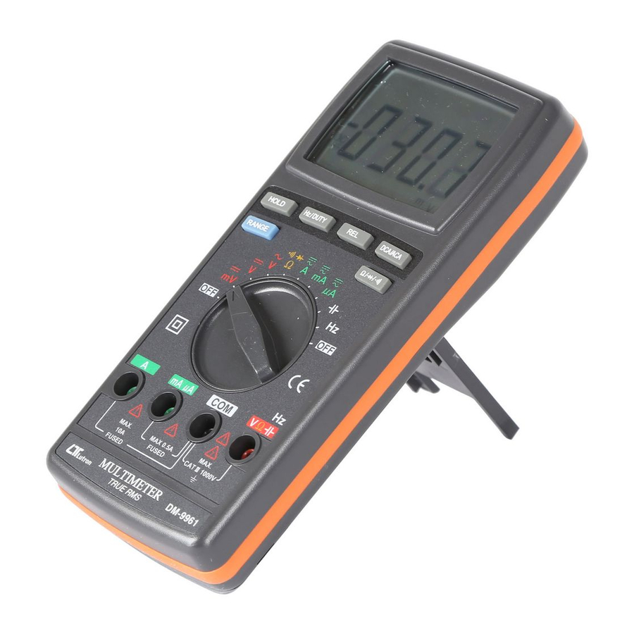
Page 9: Front Panel Description
3. FRONT PANEL DESCRIPTION Fig. 1... - Page 10 Fig. 1 3-1 Display 3-2 HOLD button 3-3 Hz/DUTY button 3-4 REL button 3-5 DCA/ACA button 3-6 RANGE button 3-7 Ohm/Diode/Buzzer button 3-8 Function rotary switch 3-9 10A input terminal 3-10 mA/uA input terminal 3-11 COM input terminal 3-12 Voltage/Ohm/Cap./Hz input terminal 3-13 Battery compartment/Cover 3-14 Stand...
-
Page 11: Precautions & Preparations For Measurement
4. PRECAUTIONS & PREPARATIONS FOR MEASUREMENT 1)Ensure that the 006 DC 9V battery are connected with the right polarity and placed in the battery compartment correctly. 2)Place the Red & Black Test Leads into the proper input terminal before making measurement. 3)Remove either of the test leads from the circuit when changing the measurement range. -
Page 12: Measuring Procedure
5. MEASURING PROCEDURE 5-1 Symbols & units of display Symbols Descriptions Units AUTO Appears when selecting " Automatic range " mode. Appears when selecting DC mode. ( DC voltage or DC current ) Appears when selecting AC mode. ( AC voltage or AC current ) HOLD Appears when the "... -
Page 13: Dc Voltage, Ac Voltage Measurement
5-2 DC Voltage, AC voltage Measurement 1)Connect BLACK test lead into " COM " terminal ( 3-11, Fig. 1 ). 2)Connect RED test lead into " V " terminal ( 3-12, Fig. 1 ). 3)a. Select the " Function rotary switch " ( 3-8, Fig. 1 ) to the "... -
Page 14: Dc Current, Ac Current Measurement
4)When LCD show the " AUTO " marker, the meter is under the " auto range " mode. Meter will select the suitable measurement range automatically. * Under the operation of " auto range " mode, push the " Range button " ( 3-6, Fig. 1 ) once will execute the "... - Page 15 3)a. For the " uA " measurement ( 400 uA, 4000 uA ), select the " Function rotary switch " ( 3-8, Fig. 1 ) to " uA " position. b. For the " mA " measurement ( 40 mA, 400 mA ), select the "...
-
Page 16: Continuity Check
5-5 Continuity Check 1)Connect BLACK test lead into " COM " terminal ( 3-11, Fig. 1 ). 2)Connect RED test lead into " Ω " terminal ( 3-12, Fig. 1 ). 3)Select the " Function rotary switch " ( 3-8, Fig. 1 ) to the "... -
Page 17: Capacitance Measurement
b. When connected as shown in Fig. 3, a reverse check on the diode is made. If the diode under test is good, " .OL " will be displayed. If the diode under test is defective, " .000 " or other numbers will be displayed. -
Page 18: Frequency, Duty Measurement
4)Zero adjustment : Due to the consideration of the existing " stray capacitance " of the internal circuit board or the test alligators. For the 40 nF & 400 nF range, it should to make the zero adjustment procedures before make the measurement first. -
Page 19: Relative Measurement
Remark : Under the ACV measurement ( 5-2 ) or ACA measurement ( 5-4 ), if push the " Hz/DUTY Button " ( 3-6, Fig. 1 ) once a while , will also can measure frequency value or DUTY value of the measured ACV or ACA. -
Page 20: Maintenance
6. MAINTENANCE Remove test leads before Caution : opening the battery cover ! 6-1 Battery replacement 1)When the LCD display showing the mark of " ", it is necessary to replace the battery, However in-spec. measurement may still be made for several hours after "... -
Page 21: Replacement Of Fuse
6-3 Replacement of Fuse When make the replacement, Caution : should change the right spec. fuse. a. Fuse A - Rating : 500 mA, Size : 5 mm dia. x 20 mm To be protected the circuit from overload current at "... -
Page 22: Optional Accessories & Adapters
7. OPTIONAL ACCESSORIES and ADAPTERS Item Model Carrying Case CA-05A Humidity Adapter HA-702 Light Adapter LX-02 EMF Adapter EMF-824 Pressure Adapter PS-403 Anemometer Adapter AM-402 Tachometer Adapter TA-601 Sound Adapter SL-406 High Voltage Probe HV-40... -
Page 23: The Address Of After Service Center
8. THE ADDRESS OF AFTER SERVICE CENTER 0411-DM-9961...
Need help?
Do you have a question about the DM-9961 and is the answer not in the manual?
Questions and answers