
Related Manuals for AIMS Power SCC60-100A


Summary of Contents for AIMS Power SCC60-100A
- Page 1 AIMS Power www.aimscorp.net Solar Charge Controller Installation and Operation Manual SCC60-100A AIMS POWER Headquarters 9550 Gateway Drive Reno, NV 89521 Telephone: (775) 359-6703 Fax: (775) 359-6753 Email: Sales@aimscorp.net Techsupport@aimscorp.net...
-
Page 2: Table Of Contents
Content Contents 1. Important safety instructions ................3 2. Getting Started ....................5 3. Installation ......................9 4. Operation ......................15 5. Troubleshooting ..................... 19 6. Warranty Claim Procedure and Datasheet ........... 20... -
Page 3: Important Safety Instructions
1. Important safety instructions Save these instructions This manual contains important safety, installation and operating instructions for the MPPT solar controller. The following symbols are used throughout this manual to indicate potentially dangerous conditions or mark important safety instructions. WARNING: Indicates a potentially dangerous condition. - Page 4 Power connections must remain tight to avoid excessive heating from a loose connection. Use properly sized conductors and circuit interrupters. WARNING: A battery can present a risk of electrical shock or burn from large amounts of short-circuit current, fire, or explosion from vented gases. Observe proper precautions.
-
Page 5: Getting Started
2. Getting Started Display and parameter setting, Monitoring Function Keys Function Key Description BACK / LEFT To exit setting mode To go to previous selection DOWN To go to next selection ENTER / RIGHT To confirm the selection in setting mode or enter setting ON(RIGHT)/OFF(LEFT Press for 2 seconds it will turn on/off the DC load... - Page 6 Setting Battery Type...
- Page 7 2.1 Overview The MPPT controller is an advanced maximum power point tracking solar battery charger. The controller features a smart tracking algorithm that finds and maintains operation at the solar array peak power point, maximizing energy harvest. The MPPT controller charging process has been optimized for long battery life and improved system performance.
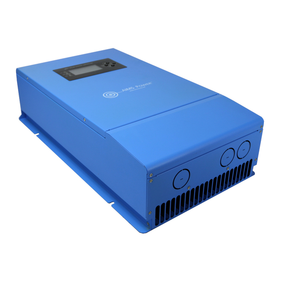
- Page 8 1. Heatsink Aluminum heatsink to dissipate controller heat 2. Mounting hole Keyhole slot for mounting 3. Setting switches Four setting switches to configure operation of the MPPT controller 4. Solar positive terminal Power connection for solar (+) Solar negative terminal Power connection for solar (-) 5.
-
Page 9: Installation
3. Installation 3.1 General Information The mounting location is important to the performance and operating life of the controller. The environment must be dry and protected from water ingress. If required, the controller may be installed in a ventilated enclosure with sufficient air flow. Never install the controller in a sealed enclosure. - Page 10 3.2 Controller Installation Step 1-Remove the wiring box cover CAUTION: Shock Hazard Disconnect all power sources to the controller before removing the wiring box cover. Never remove the cover when voltage exists on any of the power connections. Use a #4 Phillips screw driver to remove the four screws that secure the wiring box cover as show in figure below.
- Page 11 Absorption charge Battery type Bulk charge stage Float charge stage stage 14.2 14.4 13.7 14.3 14.5 13.7 Sealed 14.4 14.6 13.7 Flooded 14.6 14.8 13.5 Lithium/Lifepo4 13.7-15 Same as bulk charge voltage- Same as bulk charge voltage User define 10.0-15V 10.0-15V 10.0-15 Battery type: The most common battery type associated with the specified charging...
- Page 12 Copper 5AWG 6AWG Copper 4AWG 5AWG 100A Copper 4AWG 5AWG...
- Page 13 Power Wire Connection WARNING: Shock Hazard The solar PV array cannot produce open-circuit voltages in excess of 155V DC when in sunlight. Verify that the solar input breaker or disconnect has been opened (disconnected) before installing the system wires. Model: 20A 30A Model: 40A Model: 60A 80A 100A Connect the six power conductors shown in figure above the following steps:...
- Page 14 Power-Up WARNING: Risk of Damage Connecting the solar array to the battery terminal will permanently damage the controller. WARNING: Risk of Damage Connecting the solar array or battery connection with reverse polarity will permanently damage the controller. Confirm that the Solar and Battery polarities are correct. ...
-
Page 15: Operation
4. Operation The MPPT controller is fully automatic. After installation is completed, there are few operator tasks to perform. However, the operator should be familiar with the operation and care of the controller as described in this section. 4.1 The MPPT controller utilizes Solar Maximum Power Point Technology Tracking (MPPT) technology to extract maximum power from the solar array. - Page 16 Bulk Charge Stage In bulk charge stage, the battery is not at 100% state of charge and battery voltage has not yet charged to the absorption voltage set-point. The controller will deliver 100% of available solar power to recharge the battery. The green LED will blink once 0.5 second during bulk charging.
- Page 17 4.4 Protections, Faults and Alarms The MPPT controller protections and automatic recovery are important features that ensure the safe operation of the system. Additionally, the controller features real-time self-diagnostics that report Fault and Alarm conditions as they occur. Faults are events or conditions that require the controller to cease operation. A Fault usually occurs when a limit such as voltage, current, or temperature has been surpassed.
- Page 18 Uncalibrated The controller was not factory calibrated. Return the controller to an authorized dealer for service. Inspection and Maintenance The following inspections are recommended two times per year for best long-term performance. System Inspection Confirm the controller is securely mounted in a clean and dry environment. ...
-
Page 19: Troubleshooting
5.Troubleshooting Battery Charging and Performance Issues Problem: No LCD or LED indications, controller does not appear to be power. Solution: With a multi-meter, check the voltage at the battery terminals on the controller. Battery voltage must be 9 VDC or greater. If the voltage on the battery terminals of the controller is between 9 and 60 VDC and no LED or LCD indicate, contact your authorized dealer for service. -
Page 20: Warranty Claim Procedure And Datasheet
Power® of the refusal. If you accept the package, make sure it is noted on the carrier’s delivery record in order for AIMS Power® to file a damage claim. Save the merchandise and the original box and packing it arrived in; notify AIMS Power®... - Page 21 INCOMPLETE, SCRATCHED or DAMAGED CONDITION – AIMS Power® reserves the right to refuse crediting the customer’s account and the product will be returned to the customer.
- Page 22 This warranty only applies to AIMS Power branded products. All other name brand products are warranted by and according to their respective manufacturer. Please do not attempt to return non-AIMS Power branded products to AIMS Power. For additional products such as:...
- Page 23 Data Sheet Model SCC20A MPPT SCC30A MPPT SCC40AMPPT SCC60AMPPT SCC80AMPPT SCC100AMPPT Solar System Voltage 12V/24V 12V/24V/36V/48V Electrical 15~155Vdc@12V 34~155Vdc@24V 18~100Vdc@12V PV operating voltage 50~155Vdc@36V 34~100Vdc@24V 60~155Vdc@48V 100Vdc 155Vdc Max. PV open circuit voltage 12V 500W 12V 800W 12V 1200W 12V 1400W 24V 1000W 24V 1700W 24V 2400W...
Need help?
Do you have a question about the SCC60-100A and is the answer not in the manual?
Questions and answers