
Related Manuals for Emerson Net Safety Millennium II


Summary of Contents for Emerson Net Safety Millennium II
- Page 1 Reference Manual Part Number: MAN-0076, rev. 09 Release: June 2016 Millennium II Multi-Channel Transmitter...
- Page 3 Important Instructions Net Safety Monitoring, Inc (Net Safety) designs, manufactures and tests products to function within specific conditions. Because these products are sophisticated technical instruments, it is important that the owner and operation personnel must strictly adhere both to the information printed on the product nameplate and to all instructions provided in this manual prior to installation, operation, and maintenance.
- Page 4 Net Safety and the Net Safety logo are registered trademarks of Net Safety Monitoring, Inc. The Emerson logo is a trademark and service mark of the Emerson Electric Company. Copyright © 2016 by Rosemount, Shakopee, MN.
- Page 5 Warranty 1. Limited Warranty. Subject to the limitations contained in Section 10 (Limitation of Remedy and Liability) herein, Seller warrants that (a) the licensed firmware embodied in the Goods will execute the programming instructions provided by Seller; (b) that the Goods manufactured by Seller will be free from defects in materials or workmanship under normal use and care;...
-
Page 7: Table Of Contents
Reference Manual Table of Contents MAN-0076 Revision 09 June 2016 Contents Section 1 : Introduction ..............1 Models covered ......................1 Service support ......................1 Return of material......................1 Product recycling/disposal .................... 1 Section 2 : Installation ..............2 Unpacking and inspection .................... 2 Dimensions ........................ - Page 8 Table of Contents Reference Manual June 2016 MAN-0076, Revision 09 4.14 Manual reset ....................... 22 4.15 Self-test relay......................22 4.16 Sensor upper limit (range) ..................23 4.17 Select gas type ......................23 4.18 Calibration gas value....................24 4.19 Serial number and firmware version ................24 4.20 Exit ..........................
- Page 9 Reference Manual Table of Contents MAN-0076 Revision 09 June 2016 11.3 FC Models ........................43 11.3.1 North American .................... 43 11.3.2 IECEx (aluminum) ..................43 11.3.3 IECEx (stainless) .................... 43 Section 12 : Ordering information ..........44 12.1 M21 single channel transmitter .................. 44 12.2 M22 dual channel transmitter ..................
-
Page 11: Section 1: Introduction
Modbus RTU digital. Service support Technical support for this product can be provided by contacting your local Emerson Process Management representative or by contacting the Technical Support department at +1 866 347 3427 (toll free) or Safety.CSC@Emerson.com. -
Page 12: Section 2: Installation
Installation Reference Manual June 2016 MAN-0076, Revision 09 Section 2: Installation Unpacking and inspection Carefully remove all of the components from the packaging and verify them against the enclosed packing list. Inspect all components for any obvious damage such as broken or loose parts. If you find any components missing or damaged, notify your local Net Safety representative or the factory immediately. -
Page 13: Faceplate Rotation
Reference Manual Installation MAN-0076, Revision 09 June 2016 Ensure the orientation allows proper wiring and adequate wire length inside the transmitter enclosure. When determining suitable enclosure orientation for specific applications, installers should observe all local regulations and guidelines for mounting enclosures. Figure 2-2 Different enclosure orientations 2.3.2 Faceplate rotation... -
Page 14: Wiring
Installation Reference Manual June 2016 MAN-0076, Revision 09 Insert metal standoffs in the appropriate mounting holes Tighten metal standoffs with ¼” hex tool to secure electronics module Reconnect wiring Replace faceplate, then fit and hand tighten locking knobs to metal standoffs by turning clockwise Replace enclosure cover. -
Page 15: Terminal Connection
Reference Manual Installation MAN-0076, Revision 09 June 2016 Wiring codes and regulations may vary. Wiring must comply with all applicable regulations relating to the installation of electrical equipment in a hazardous area and is the responsibility of the installer. If in doubt, consult a qualified official before wiring the system. -
Page 16: Internal Ground Screw
Installation Reference Manual June 2016 MAN-0076, Revision 09 · Detection instruments · Customer connected equipment · Wiring Net Safety designs and manufactures its detection equipment under rigid quality control management systems and makes every effort to design for the harshest of industrial environments. The other components of the system –... - Page 17 Reference Manual Installation MAN-0076, Revision 09 June 2016 · The jacket and shielding of the cable should be stripped back to permit the seal to form around the individual wires. This will prevent air particles and water leakage through the inside of the shield and into the enclosure ·...
-
Page 18: Remotely Mounted Sensors Jumper Configuration
Installation Reference Manual June 2016 MAN-0076, Revision 09 Always ensure that JP3 and JP4 jumpers are in the correct position depending on the current output configuration chosen 2.4.9 Remotely mounted sensors jumper configuration Sensor separation from the transmitter may extend up to 2000 feet (600 meters) in which case a junction box is required. -
Page 19: Remote Reset
Reference Manual Installation MAN-0076, Revision 09 June 2016 Sensor Terminals Transmitter power terminals Sensor wires Transmitter sensor board terminal Transmitter terminal Function designation designation White +Vdc (from transmitter) Remote Reset SigA +Vdc (10.5-32Vdc) Power (+) Blue SigB Power (-) Black 4-20 (CH1) Channel #1 current loop output Green... -
Page 20: Sensor Separation/Remote Mounting Of Sensor
Installation Reference Manual June 2016 MAN-0076, Revision 09 Figure 2-8 Remote reset wiring Sensor separation/remote mounting of sensor When it is necessary to mount the sensor remotely (separated from transmitter), by way of junction box and conduit, it is important that the installer follow the necessary requirements and guidelines relating to sensor separation and cable selection. -
Page 21: Wiring Diagrams
Reference Manual Installation MAN-0076, Revision 09 June 2016 2.5.1 Wiring diagrams Wiring drawings show general ways in wiring the system for analog signal output. Consult qualified personnel on specific wiring requirements. Figure 2-10 Non-isolated terminal connection Installation... -
Page 22: Installation Checklist
Installation Reference Manual June 2016 MAN-0076, Revision 09 Figure 2-11 Isolated terminal connection Installation checklist Review the following checklist prior to turning the power on to the transmitter after installation has been completed: □ Ensure that the transmitter and sensor are properly and firmly mounted. □... -
Page 23: Section 3: Operation
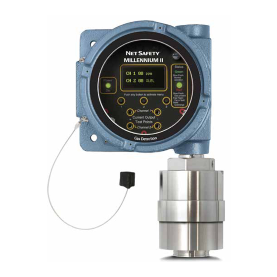
Reference Manual Operation MAN-0076, Revision 09 June 2016 Section 3: Operation Transmitter and faceplate description Figure 3-1 Faceplate description 3.1.1 Display The Millennium II is equipped with an Organic LED (OLED) display. It allows the user to see the concentration of gas present for each individual channel and the various options offered. The display has a wide temperature rating and will operate well in lowly lit conditions. -
Page 24: Current Loop Measurement (Test Jacks)
Operation Reference Manual June 2016 MAN-0076, Revision 09 3.1.3 Current loop measurement (test jacks) Do not open the transmitter, sensor, or junction box enclosure when in a classified area or when an explosive atmosphere may be present unless the power to the transmitter has been removed. For convenience, a pair of test jacks for each analog output is provided on the front face of the display module. -
Page 25: Section 4: Programming
Reference Manual Programming MAN-0076, Revision 09 June 2016 Section 4: Programming Menu options The main menu provides access to various functional settings/options, as seen in the list below. Each menu option has a submenu, where configuration is completed. Calibrate Sensor Enable/Disable Channels Set Alarm Level Set Relay Option (available on relay models) - Page 26 Programming Reference Manual June 2016 MAN-0076, Revision 09 Figure 4-1 Programming flowchart Enter Main Menu? Calibrate Sensor? Select Display Selftest Relay? Language? Enable/Disable Modbus Setup Sensor Upper Limit Channels? (Range) Set Alarm Level? Setup Current Date? Select Gas Type Set Relay Option? Setup Current Time? Cal Gas Value Relay Assignment?
-
Page 27: Calibrate Sensor
Reference Manual Programming MAN-0076, Revision 09 June 2016 Calibrate sensor This menu function allows the user to perform a calibration on the connected sensor. Refer to Section for the calibration procedure. Enable/Disable channels This option allows the Millennium II Transmitter channels to be enabled or disabled. The default value is channel 1 (CH1) enabled for single sensor models (model M21) while channel 2 (CH2) is permanently disabled. -
Page 28: Set Relay Option
Programming Reference Manual June 2016 MAN-0076, Revision 09 Use switch 1 to increase the existing values representing previously set alarm levels/points and switch 2 to highlight and scroll across values. After setting desired alarm points, select “Exit” at each menu stage (sub menu and main menu). Apply test gas to confirm alarm level settings. - Page 29 Reference Manual Programming MAN-0076, Revision 09 June 2016 Prior to assigning relays, configure the alarm levels (points). See Section ‘4.2.4 Viewing and setting alarm levels (points)’, and then follow the steps and example below to configure the Alarm relays. Also see Table 3, Example and Table 4.
-
Page 30: Alarm Mode Setting
Programming Reference Manual June 2016 MAN-0076, Revision 09 Alarm mode setting Only used on Oxygen (ST341) sensors This option is available for detecting oxygen levels. The user is allowed to set up two Alarm points/level (normal oxygen level is 20.9 %) under three available Alarm Modes. These Alarm Modes are: Above- Above, Below-Below and Below-Above. -
Page 31: Setup Current Date
Reference Manual Programming MAN-0076, Revision 09 June 2016 Activate the enter key (switch 3) when the desired value is displayed. After setting the baud rate, exit this sub menu option using switch 3, and then activate the down arrow key (switch 2) to highlight ‘Parity Bit’. Activate switch 3, then activate the up key (switch 2), or the down key (switch 1) to choose a value. -
Page 32: Manual Reset
Programming Reference Manual June 2016 MAN-0076, Revision 09 Activate the enter key (switch 3) to display the sub menu. The most recent event will be displayed. Select the up arrow key (switch 1) and the down arrow key (switch 2) to toggle through all past events. -
Page 33: Sensor Upper Limit (Range)
Reference Manual Programming MAN-0076, Revision 09 June 2016 unwanted alarm activation. Enable external equipment once testing is completed. The Self-test relay option continuously turns relays on and off to ensure that they are functioning properly. The Fault Relay is tested first, automatically followed by tests on Relay 1, 2, and 3. After the relays have been tested, “Relay Test Complete”... -
Page 34: Calibration Gas Value
Programming Reference Manual June 2016 MAN-0076, Revision 09 4.18 Calibration gas value This option allows the user to select the calibration gas value in the transmitter main menu. Although it is recommended that 50% span gas should be used for calibration, for some sensors, the transmitter will allow tolerance/flexibility in the calibration gas available;... -
Page 35: Section 5: Calibration Procedure
Reference Manual Calibration procedure MAN-0076, Revision 09 June 2016 Section 5: Calibration procedure Full calibration procedure Prior to attempting calibration read and understand the calibration procedure below. Also see Figure for additional reference. The following calibration procedure should be followed to ensure an accurate correlation between the output signal and the gas concentration. - Page 36 Calibration procedure Reference Manual June 2016 MAN-0076, Revision 09 The “Zero” calibration option is selected if the sensor is only being zeroed (this not a complete calibration) It does not require the application of span gas, as only the sensor’s zero point is adjusted. Ensure that no contaminants are present, if the surrounding air is to be used for Zeroing.
- Page 37 Reference Manual Calibration procedure MAN-0076, Revision 09 June 2016 Figure 5-1 Calibration flowchart Enter Main Menu? Note: Calibration process is identical for Channel #2 Calibrate Sensor? Remove air canister (if used) - Zero calibration complete, full calibration continue to next block CH 1: Apply 50% span gas Calibrate Sensor #1 Note: Some sensor types can...
-
Page 38: Status Conditions During Calibration
Calibration procedure Reference Manual June 2016 MAN-0076, Revision 09 Status conditions during calibration Condition Current output LED indication Relay outputs Green Fault Alarm Sensor is zeroing itself 3 mA Solid Normal state Normal state Sensor is waiting until it detects application 3.3 mA Very fast Normal state... -
Page 39: Section 6: Monitoring And Outputs
Reference Manual Monitoring and outputs MAN-0076, Revision 09 June 2016 Section 6: Monitoring and outputs Analog 4-20mA A 4-20 mA current output is used to transmit the transmitter and sensor status and fault codes to other devices. This output can be wired for isolated or non-isolated operation. A 4.0 mA output indicates normal operation;... -
Page 40: Relays (Optional)
Monitoring and outputs Reference Manual June 2016 MAN-0076, Revision 09 Figure 6-1 Analog/HART wiring Relays (Optional) Optional electromechanical relays have Form-C SPDT contacts rated 5 Amps at 30 VDC/ 250 VAC. There are four physical relays; one Fault and three Alarm relays. These relays have Normally Open and Normally Closed contacts at the output terminals. -
Page 41: Rs-485 Modbus Rtu (Optional)
Reference Manual Monitoring and outputs MAN-0076, Revision 09 June 2016 The fault relay is normally energized when no fault conditions are present and is set up for non-latching. The operation of the fault relay is not configurable. The Millennium II transmitter provides various fault conditions to indicate that the transmitter or connected sensor(s) are not operating as expected. -
Page 42: Modbus Registers
Monitoring and outputs Reference Manual June 2016 MAN-0076, Revision 09 6.4.1 Modbus registers Reg# Meaning Readable Writeable 40001 Concentration value as calculated by sensor (RTUsensor_out), Channel 1 40002 Sensor status (RTUsensor_stat), Channel 1 40003 Temperature of sensor element housing in Kelvin (RTU temperature), Channel 1 40004 RFU, Channel 1, always read as 0x0000 40005... -
Page 43: Transmitter Output Operation
Reference Manual Monitoring and outputs MAN-0076, Revision 09 June 2016 Transmitter output operation The following table outlines the operation of the outputs of the Millennium II transmitter under different conditions. These outputs include the analog output, LED indications, and the relay outputs. For the outputs’... -
Page 44: Fault Conditions
Monitoring and outputs Reference Manual June 2016 MAN-0076, Revision 09 The fault detection circuitry does not monitor the operation of external response equipment or external wiring to the transmitter. It is important that external equipment and wiring be checked periodically to ensure they are operational. Fault conditions Fault conditions will override any alarm conditions because the sensor may be unable to detect a gas exposure reliably, as such, the alarm relay will not provide an output. -
Page 45: Sensor Fault Conditions
Reference Manual Monitoring and outputs MAN-0076, Revision 09 June 2016 6.7.2 Sensor fault conditions Fault conditions that the various Millennium II sensors detect are as follows: Fault condition SC310 SC311 ST322 ST332 ST340 ST320 ST330 ST341 ST360 Zero calibration failure Span calibration failure Low temperature High temperature... -
Page 46: Section 7: Maintenance
Maintenance Reference Manual June 2016 MAN-0076, Revision 09 Section 7: Maintenance Periodic response check Net Safety Monitoring recommends that a bump test be performed every 90 days to ensure continued functionality and accuracy of the detection system. Full calibration is recommended when the sensor fails to meet acceptable accuracy standards. -
Page 47: Spare Parts And Accessories
Reference Manual Maintenance MAN-0076, Revision 09 June 2016 Spare parts and accessories Description Part Number 3/4 NPT ATEX certified plug - Aluminum CP-AL-002 3/4 NPT ATEX certified plug - Stainless Steel CP-SS-001 Aluminum separation kit JB-MPD-A Stainless Steel separation kit JB-MPD-S Magnet assembly MAGNET-1... - Page 48 Maintenance Reference Manual June 2016 MAN-0076, Revision 09 Description Part Number 3" Pipe Mounting kit - All Millennium II & ECO-SENSE Gas Detectors UN-MK-33 (stainless steel) Maintenance...
-
Page 49: Section 8: Electrostatic Sensitive Device
Reference Manual Electrostatic sensitive device MAN-0076, Revision 09 June 2016 Section 8: Electrostatic sensitive device Definition: Electrostatic discharge (ESD) is the transfer, between bodies, of an electrostatic charge caused by direct contact or induced by an electrostatic field. The most common cause of ESD is physical contact. Touching an object can cause a discharge of electrostatic energy. -
Page 50: Section 9: Wire Resistance Table
Wire resistance table Reference Manual June 2016 MAN-0076, Revision 09 Section 9: Wire resistance table Distance AWG #20 AWG #18 AWG #16 AWG #14 Feet (Meters) 0.5 mm 0.8 mm 1.0 mm 2.0 mm 100 (30.5) 1.02 0.64 0.40 0.25 200 (61) 2.03 1.28... -
Page 51: Section 10: Specifications
Reference Manual Specifications MAN-0076, Revision 09 June 2016 Section 10: Specifications 10.1 Electrical 10.1.1 Operating voltage range 10.5 to 32 VDC 18 to 32 VDC (HART versions only) 10.1.2 Power consumption 2.4 W @ 24 VDC (average - varies by sensor types/quantities) 10.1.3 EMC compliance EN 50270:2006 per EMC directive 2004/108/EC... -
Page 52: Weight
Specifications Reference Manual June 2016 MAN-0076, Revision 09 10.3.3 Weight Aluminum: 5.5 lbs (2.5 kg) Stainless Steel: 7.0 lbs (3.2 kg) 10.4 Warranty 3 years Specifications... -
Page 53: Section 11: Certifications
Reference Manual Certifications MAN-0076, Revision 09 June 2016 Section 11: Certifications 11.1 North American Class I, Division 1, Groups BCD T5 Class I, Zone 1, AEX/Ex d IIB+H -50 °C ≤ Ta ≤ + 85 °C NEMA Type 4X/IP67 FM6320, ANSI/ISA 12.13.01, CSA 22.2 No. 152:2006 11.2 IECEx Ex d IIB+H... -
Page 54: Section 12: Ordering Information
Ordering information Reference Manual June 2016 MAN-0076, Revision 09 Section 12: Ordering information 12.1 M21 single channel transmitter Model Description Millennium II Single Channel Transmitter Output Description Analog Output Analog and Digital RS485 Modbus RTU Protocol Outputs Analog and HART Protocol Outputs Analog, HART Protocol and Relay Outputs Analog and Relay Outputs Analog, Relay and Digital RS485 Modbus RTU Protocol Outputs... -
Page 55: M22 Dual Channel Transmitter
Reference Manual Ordering information MAN-0076, Revision 09 June 2016 12.2 M22 dual channel transmitter Model Description Millennium II Dual Channel Transmitter Output Description Analog Output Analog and Digital RS485 Modbus RTU Protocol Outputs Analog and Relay Outputs Analog, Relay and Digital RS485 Modbus RTU Protocol Outputs Enclosure Description Aluminum... - Page 56 ©2016 Emerson Process Management. All rights reserved. The Emerson logo is a trademark and service mark of Emerson Electric Co. Rosemount is a mark of one of the Emerson Process Management family of companies. All other marks are property of their respective owners.
Need help?
Do you have a question about the Net Safety Millennium II and is the answer not in the manual?
Questions and answers
MILLENNIUM 2 GAS DETECTION SENSOR