
Related Manuals for Sentiotec Panorama Small


Summary of Contents for Sentiotec Panorama Small
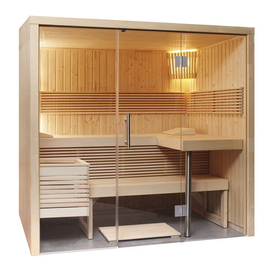
- Page 1 Montageanleitung Assembly instructions Instructions d`installation Symbolfoto PANORAMA SMALL Elementsauna 213 x 160 x 201 cm Version 12/18 Artikel-Nr.: 1-030-309...
- Page 2 Lesen Sie diese Montageanleitung gut durch und bewahren Sie sie in der Nähe der Sauna auf. So können Sie jederzeit Produktinformationen nachlesen. Sie finden diese Montageanleitung auch im Downloadbereich unserer Webseite auf www.sentiotec.com/downloads. Achtung! Der Elektroanschluss darf nur durch eine Elektrofachkraft oder eine vergleichs- weise qualifizierte Person ausgeführt werden.
- Page 3 ● Holz ist ein Naturprodukt, das trotz guter Lagerung aufquellen, schwinden oder sich verziehen kann. Aus diesem Grund kann es vorkommen, dass bei der Montage etwas Kraft aufgebracht werden muss. ● Alle Verschraubungen müssen vorgebohrt werden. Benötigtes Werkzeug ● Hammer und Beilageholz oder einen Gummihammer ●...
- Page 4 Montageanleitung Wartung und Reinigung ● Die Sauna sollte mit einem feuchten Tuch gereinigt werden. Verwenden Sie nur warmes Wasser - keine Reinigungsmittel. ● Wird die Sauna längere Zeit nicht benutzt, empfehlen wir, die Kabine einmal im Monat aufzuheizen. Harzgallen sind kein Reklamationsgrund. Da in Fichtenholz immer wieder Harz- gallen vorkommen und man beim Aussortieren nicht erkennen kann in welcher Tiefe diese sich befinden.
- Page 5 Stückliste PANORAMA SMALL Bodenrahmen Glasfront 1 Bodenrahmen 4 x 8 x 151,5 cm 1 Glaselement 195,2 x 69,4 x 0,8 cm 1 Bodenrahmen 4 x 8 x 206,5 cm 1 Glaselement 195,2 x 69,4 x 0,8 cm 1 Bodenrahmen 4 x 8 x 150 cm mit Bohrung für Türbänder...
- Page 6 Montageanleitung Länge: 206,5 cm Länge: 150 cm Länge: 151,5 cm Abb 1.1 Abb 1.3 Abb 1.2 Eckverbindungsleiste mit Schrauben: 5 x 90 mm an Wandelementen W2 + W4 befestigen.
- Page 7 Abb 1.5 Abb 1.4 Abb 1.7 Abb 1.6 Schrauben: 3,2 x 40 mm Abb 1.8...
- Page 8 Montageanleitung Abb 1.9 Schrauben: 3,5 x 40 mm Abb 1.10 Abb 1.11 Schrauben: 5 x 80 mm Abb 1.12...
- Page 9 Dachverschraubung Schrauben: 5 x 80 mm Abb 1.13 Schrauben: 3,5 x 40 mm Abb 1.14 Abb 1.15 Schrauben: 5 x 80 mm Abb 1.16...
- Page 10 Montageanleitung 3 x Schrauben 5 x 70 mm 2 x Schrauben 4 x 60 mm 82 cm Abb 1.17 Abb 1.18 10 mm Abb 1.19...
- Page 11 6 x Schrauben 2,5 x 25 mm Abb 1.20 Niro-Fuß mit Inbusschraube festklemmen. Abb 1.21 Querbank - Ansicht von unten ! 3 x Schrauben 5 x 70 mm Abb 1.23 Abb 1.22...
- Page 12 Montageanleitung Schrauben 3,5 x 40 mm Abb 1.24 Schrauben 4 x 60 mm Querstreben links und rechts der Bank hinten montieren. Abb 1.25 Schrauben 3,2 x 30 mm Abb 1.26 Abdeckleiste senkrecht Schrauben 3,2 x 30 mm Abb 1.27...
- Page 13 2 x Schrauben 3,5 x 40 mm 25 cm Abb 1.28 Schrauben 3,5 x 40 mm Abb 1.29 Abb 1.30...
- Page 14 Montageanleitung Glasmontageleisten von oben nach unten drücken (links und rechts) Glastürbeschlag Aluleiste (mit Silikon am Boden befestigen) Abb 1.32 Abb 1.31 Obere Glasmontageleiste von rechts nach links drücken (seitl.Abstand links und rechts sollte gleich sein Abb 1.33 Schrauben 4 x 60 mm Abb 1.34...
- Page 15 Abb 1.36 Abb 1.37 Abb 1.35 Ofenschutzgitter 60 cm Innenseite Schrauben 3,5 x 40 mm Schrauben 3,5 x 40 mm Abb 1.38 Abb 1.39 Abb 1.40...
- Page 16 GRUNDRISS PANORAMA SMALL 213 x 160 x 201 cm Kabine links oder rechts aufbaubar...
- Page 17 Montageanleitung Assembly instructions Instructions d`installation Symbol photo PANORAMA SMALL Element sauna 213 x 160 x 201 cm Version 12/18 item no. 1-030-309...
- Page 18 These assembly instructions can also be found in the downloads section of our website: www.sentiotec.com/downloads. Attention! The electrical connection may only be performed by a qualified electrician or similarly qualified person.
-
Page 19: Tools Required
● Wood is a natural product that can swell, shrink or warp, despite good storage. For this reason, some force may be necessary during the installation. ● All screw fittings must be pre-drilled. Tools required ● Hammer with a wooden head or a mallet ●... - Page 20 Assembly instructions Maintenance and cleaning ● The sauna should be cleaned with a damp cloth. Only use warm water – no cleaning products. ● We recommend heating the cabin once a month if the sauna is not used for a long time. Pitch pockets are not grounds for return, since they can always appear in spruce wood and the depth at which they lie cannot be detected during the sorting-out process.
- Page 21 PANORAMA SMALL parts list Base frame Glass front 1 floor frame 4 x 8 x 151.5 cm 1 glass element 195.2 x 69.4 x 0.8 cm 1 floor frame 4 x 8 x 206.5 cm 1 glass element 195.2 x 69.4 x 0.8 cm...
- Page 22 Assembly instructions Length: 206.5 cm Length: 150 cm Length: 151.5 cm Fig. 1.1 Fig. 1.3 Fig. 1.2 Corner connecting strip with screws: 5 x 90 mm fasten to wall elements W2 + W4.
- Page 23 Fig. 1.5 Fig. 1.4 Fig. 1.7 Fig. 1.6 Screws: 3.2 x 40 mm Fig. 1.8...
- Page 24 Assembly instructions Fig. 1.9 Screws: 3.5 x 40 mm Fig. 1.10 Fig. 1.11 Screws: 5 x 80 mm Fig. 1.12...
- Page 25 Roof screw connection Screws: 5 x 80 mm Fig. 1.13 Screws: 3.5 x 40 mm Fig. 1.14 Fig. 1.15 Screws: 5 x 80 mm Fig. 1.16...
- Page 26 Assembly instructions 3 x screws 5 x 70 mm 2 x screws 4 x 60 mm 82 cm Fig. 1.17 Fig. 1.18 10 mm Fig. 1.19...
- Page 27 6 x screws 2.5 x 25 mm Fig. 1.20 Clam the stainless steel foot with an allen key. Fig. 1.21 Cross bench - View from below! 3 x screws 5 x 70 mm Fig. 1.23 Fig. 1.22...
- Page 28 Assembly instructions screws 3.5 x 40 mm Fig. 1.24 screws 4 x 60 mm Mount the cross struts on the left and right of the rear bench. Fig. 1.25 screws 3.2 x 30 mm Fig. 1.26 Vertical cover strip screws 3.2 x 30 mm Fig.
- Page 29 2 x screws 3.5 x 40 mm 25 cm Fig. 1.28 screws 3.5 x 40 mm Fig. 1.29 Fig. 1.30...
- Page 30 Assembly instructions Push the glass mounting rails down (left and right) Glass door fitting Aluminium strip (fasten to the floor with silicone) Fig. 1.32 Fig. 1.31 Push the top glass mounting rail from right to left (the side distance on the left and right should be the same) Fig.
- Page 31 Fig. 1.36 Fig. 1.37 Fig. 1.35 Heater protection grille 60 cm Inside Screws 3.5 x 40 mm Screws 3.5 x 40 mm Fig. 1.38 Fig. 1.39 Fig. 1.40...
- Page 32 FLOOR PLAN OF PANORAMA SMALL 213 x 160 x 201 cm The cabin can be set up on the left or right.
- Page 33 Instructions de montage Assembly instructions Instructions d`installation Photo symbolique Sauna à base d’éléments PANORAMA SMALL 213 x 160 x 201 cm Version 12/18 Référence 1-030-309...
- Page 34 Vous avez ainsi accès à tout moment aux informations sur le produit. Vous trouverez également ces instructions de montage dans la rubrique de téléchargement de notre site Internet www.sentiotec.com/downloads. Attention ! Seul un électricien spécialisé ou une personne ayant une qualification similaire est habilité...
- Page 35 ● Malgré un stockage correct, le bois est un produit naturel qui peut gonfler, se con- tracter ou se déformer. C’est pourquoi il peut arriver que vous ayez à appliquer de la force lors du montage. ● Tous les raccords vissés doivent être préalésés. Outils requis ●...
- Page 36 Instructions de montage Entretien et nettoyage ● Le sauna doit être nettoyé au moyen d’un chiffon humide. N’utilisez que de l’eau chaude, pas de détergent. ● Si le sauna n’est pas utilisé pendant une période prolongée, nous recommandons de chauffer la cabine une fois par mois. Les poches de résine ne constituent pas un motif de réclamation.
- Page 37 Nomenclature PANORAMA SMALL Cadre de plancher 161,7 x 7 x 2,5 cm 1 cadre de plancher 4 x 8 x 151,5 cm Façade vitrée 1 cadre de plancher 4 x 8 x 206,5 cm 1 élément en verre 195,2 x 69,4 x 0,8 cm 1 cadre de plancher 4 x 8 x 150 cm 1 élément en verre 195,2 x 69,4 x 0,8 cm...
- Page 38 Instructions de montage Longueur : 206,5 cm Longueur : 150 cm Longueur : 151,5 cm Fig 1.1 Fig 1.3 Fig 1.2 Fixer la baguette de raccordement d'angle avec les vis : 5 x 90 mm aux éléments muraux W2 + W4.
- Page 39 Fig 1.5 Fig 1.4 Fig 1.7 Fig 1.6 Vis : 3,2 x 40 mm Fig 1.8...
- Page 40 Instructions de montage Fig 1.9 Vis : 3,5 x 40 mm Fig 1.10 Fig 1.11 Vis : 5 x 80 mm Fig 1.12...
- Page 41 Vissage du toit Vis : 5 x 80 mm Fig 1.13 Vis : 3,5 x 40 mm Fig 1.14 Fig 1.15 Vis : 5 x 80 mm Fig 1.16...
- Page 42 Instructions de montage 3 vis 5 x 70 mm 2 vis 4 x 60 mm 82 cm Fig 1.17 Fig 1.18 10 mm Fig 1.19...
- Page 43 6 vis 2,5 x 25 mm Fig 1.20 Serrer le pied Niro avec une vis six pans. Fig 1.21 Banc transversal - vue d’en bas ! 3 vis 5 x 70 mm Fig 1.23 Fig 1.22...
- Page 44 Instructions de montage Vis 3,5 x 40 mm Fig 1.24 Vis 4 x 60 mm Monter les traverses à gauche et à droite du banc arrière. Fig 1.25 Vis 3,2 x 30 mm Fig 1.26 Baguette de recouvre- ment verticale Fig 1.27 Vis 3,2 x 30 mm...
- Page 45 2 vis 3,5 x 40 mm 25 cm Fig 1.28 Vis 3,5 x 40 mm Fig 1.29 Fig 1.30...
- Page 46 Instructions de montage Appuyer les baguettes de montage de verre du haut vers le bas (à gauche et à droite) Ferrure de porte en verre Baguette en alu (fixer au sol avec du silicone) Fig 1.31 Fig 1.32 Appuyer la baguette de montage de verre de la droite vers la gauche (la distance latérale doit être identique à...
- Page 47 Fig 1.36 Fig 1.37 Fig 1.35 Grilles de protection de poêle 60 cm Côté intérieur Vis 3,5 x 40 mm Vis 3,5 x 40 mm Fig 1.38 Fig 1.39 Fig 1.40...
- Page 48 PLAN PANORAMA SMALL 213 x 160 x 201 cm Cabine à installer à gauche ou à droite...
- Page 49 GmbH | Division of Harvia Group | Oberregauer Straße 48, A-4844 Regau T +43 (0) 7672/277 20-567 | F -801 | info@sentiotec.com | www.sentiotec.com...
Need help?
Do you have a question about the Panorama Small and is the answer not in the manual?
Questions and answers