Table of Contents
Advertisement
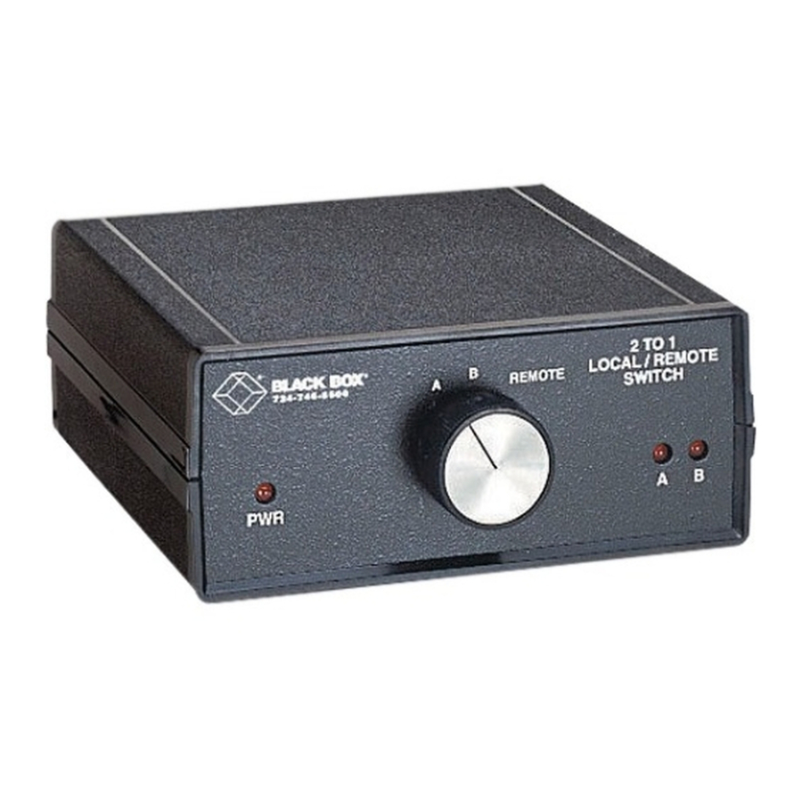
Local/Remote Electronic Switches
CUSTOMER
SUPPORT
INFORMATION
B O X
B L A C K
®
6 - 5 5 0 0
7 2 4 - 7 4
P W R
Order toll-free in the U.S. 24 hours, 7 A.M. Monday to midnight Friday: 877-877-BBOX
FREE technical support, 24 hours a day, 7 days a week: Call 724-746-5500 or fax 724-746-0746
Mail order: Black Box Corporation, 1000 Park Drive, Lawrence, PA 15055-1018
Web site: www.blackbox.com • E-mail: info@blackbox.com
R
R E M O
B
A
MARCH 2000
SW980A
SW980AE
SW981A
SW981AE
SW982A
SW982AE
2 T O 1
T E
/ R E M O
L O C A L
H
S W I T C
T E
B
A
Advertisement
Table of Contents

Related Manuals for Black Box SW980A


Summary of Contents for Black Box SW980A
- Page 1 SUPPORT FREE technical support, 24 hours a day, 7 days a week: Call 724-746-5500 or fax 724-746-0746 INFORMATION Mail order: Black Box Corporation, 1000 Park Drive, Lawrence, PA 15055-1018 Web site: www.blackbox.com • E-mail: info@blackbox.com B O X B L A C K ®...
-
Page 2: Fcc/Ic/Ce Statements
FCC/IC/CE STATEMENTS FEDERAL COMMUNICATIONS COMMISSION AND INDUSTRY CANADA RADIO-FREQUENCY INTERFERENCE STATEMENTS This equipment generates, uses, and can radiate radio frequency energy and if not installed and used properly, that is, in strict accordance with the manufacturer’s instructions, may cause interference to radio communication. It has been tested and found to comply with the limits for a Class A computing device in accordance with the specifications in Subpart J of Part 15 of FCC rules, which are designed to provide reasonable protection against such interference when the equipment is... -
Page 3: Instrucciones De Seguridad
LOCAL/REMOTE ELECTRONIC SWITCHES NORMAS OFICIALES MEXICANAS (NOM) 1. Todas las instrucciones de seguridad y operación deberán ser leídas antes de que el aparato eléctrico sea operado. 2. Las instrucciones de seguridad y operación deberán ser guardadas para referencia futura. 3. Todas las advertencias en el aparato eléctrico y en sus instrucciones de operación deben ser respetadas. -
Page 4: Trademarks Used In This Manual
12. Precaución debe ser tomada de tal manera que la tierra fisica y la polarización del equipo no sea eliminada. 13. Los cables de la fuente de poder deben ser guiados de tal manera que no sean pisados ni pellizcados por objetos colocados sobre o contra ellos, poniendo particular atención a los contactos y receptáculos donde salen del aparato. -
Page 5: Table Of Contents
4.2.1 ABC and ABCDE Switches (SW980 and SW982 Units) ... 19 4.2.2 X Switches (SW981 Units) ... 19 4.3 Test Results ... 22 5. Troubleshooting ... 23 5.1 Calling Black Box ... 23 5.2 Shipping and Packaging ... 23 Contents Page... -
Page 6: Specifications
All models: Remote switching either through TTL, RS-232, RS-422/485, or other active drivers or through dry-contact closure; SW980 and SW982 models: (1) Rear-mounted 2-position DIP switch for grounding; SW981 models: (2) Rear-mounted 2-position DIP switches for grounding Front-mounted LEDs: All models: (1) for Power;... - Page 7 DC resistance must be less than 240 ohms when the dry contact is closed for the Local/Remote Electronic Switch to correctly read this condition as a “low” input. SW980A, SW981A, SW982A: From wallmount power supply PS154: Input: 120 VAC, 60 Hz; Output: 17 VAC CT;...
-
Page 8: Introduction
In addition, these switches can be controlled remotely, from a convenient out-of-sight location. The stock models available are: SW980A 115-VAC 2-to-1 Switch SW980AE 230-VAC 2-to-1 Switch SW981A 115-VAC “X”... -
Page 9: Installation And Configuration
Pins 3 through 6 of a male RJ-45 connector at the Switch end. (If you must use existing cables that do not meet these requirements, call Black Box Technical Support; we might be able to provide adapters or create a special product for you.) -
Page 10: The Setup Procedure
1. Make sure that the Switch is unplugged (is not receiving AC power). Open the Switch by unscrewing the two screws on the bottom of the unit (save these screws) and removing the top of the unit’s housing. (You will probably have to peel back the CE sticker on the bottom of the unit to get at one of the screws.) - Page 11 LOCAL/REMOTE ELECTRONIC SWITCHES REAR FRONT Figure 3-1. PCB layout of the SW980 models.
- Page 12 CHAPTER 3: Installation and Configuration REAR FRONT Figure 3-2. PCB layout of the SW981 models.
- Page 13 LOCAL/REMOTE ELECTRONIC SWITCHES FRONT Figure 3-3. PCB layout of the SW982 models. REAR...
- Page 14 If you are using a remote-switching cable that is unterminated at the Switch end, make sure that the cable is seated in the slot on the left side of the Switch’s rear panel before you put the cover back on.
- Page 15 LOCAL/REMOTE ELECTRONIC SWITCHES REMOTE Figure 3-5. Rear panel of the SW981 models. REMOTE Figure 3-6. Rear panel of the SW982 models. SERIAL PARALLEL SERIAL PARALLEL...
- Page 16 6. Set the DIP switch(es) as appropriate for your application. Refer to Table 3-1 and Figure 3-7 below, and keep in mind that OFF = UP and ON = DOWN. Table 3-1. Possible Settings for Switches S2 and S3 All 25 leads of the Local/Remote Electronic Switch’s DB25 connectors are straight- through and are isolated from one another.
- Page 17 “branch” devices (those that will share—or be intermittently accessed by—the other device) to the branch connectors (marked “A” and “B” [and “D” and “E” on the SW982]) on the Switch’s rear panel. 9B. SW981 units only: Connect the cables from the two “source” devices to the connectors on the Switch’s rear panel labeled “A”...
-
Page 18: Operation
“A” and “B” (and, for SW982 units, “D” and “E”), one after the other. Switch between branch devices by manually turning the knob on the Switch’s front panel. -
Page 19: Switches (Sw981 Units)
Refer to Figure 4-2 below: Test your Local/Remote Electronic Switch system by having each source device (“A” and “B”) send data to each destination device (“AA” and “BB”), one after the other. Switch between data pathways by manually turning the knob on the Switch’s front panel. -
Page 20: Remote Switching
Now have the common device send data to, or receive data from, branch devices “A” and “B” (and, for SW982 units, “D” and “E”), one after the other. Switch between branch devices by sending “high” and “low” electric signals to the Switch through its RJ-45 connector or its internal 4-position terminal block. - Page 21 LOCAL/REMOTE ELECTRONIC SWITCHES Table 4-1. Connector Pinouts and Signal Levels for Port Selection with the ABC Switch (SW980 Models) or Path Selection with the X Switch (SW981 Models) Pinout of the RJ-45 Connector Pinout of the 4-Position Terminal Block Signal Levels for Port Selection (SW980 Models)
- Page 22 Table 4-2. Connector Pinouts and Signal Levels for Port Selection with the ABCDE Switch (SW982 Models) Pinout of the RJ-45 Connector Pinout of the 4-Position Terminal Block Signal Levels for Port Selection Port Selected Remote Input A CHAPTER 4: Operation...
-
Page 23: Test Results
• Any software involved is configured and operating correctly. If your Switch is working properly, your system is ready to go. If the Switch fails the test, or if it should begin malfunctioning later, contact Black Box Technical Support (see Chapter 5). -
Page 24: Troubleshooting
• Package it carefully. We recommend that you use the original container. • If you are returning the Switch, please include everything you received with it. If you are shipping the Switch for repair or return, contact Black Box to get a Return Authorization (RA) number. - Page 25 NOTES...
- Page 26 © Copyright 2000. Black Box Corporation. All rights reserved. 1000 Park Drive • Lawrence, PA 15055-1018 • 724-746-5500 • Fax 724-746-0746...
Need help?
Do you have a question about the SW980A and is the answer not in the manual?
Questions and answers