Table of Contents
Advertisement
SEPTEMBER 2001
SWI080A
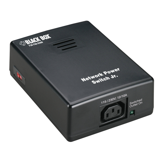
Network Power Switch Jr.
CUSTOMER SUPPORT INFORMATION
Order toll-free in the U.S.: Call 877-877-BBOX (outside U.S. call 724-746-5500)
FREE technical support 24 hours a day, 7 days a week: Call 724-746-5500 or fax 724-746-0746
Mailing address: Black Box Corporation, 1000 Park Drive, Lawrence, PA 15055-1018
Web site: www.blackbox.com • E-mail: info@blackbox.com
Advertisement
Table of Contents

Related Manuals for Black Box SWI080A


Summary of Contents for Black Box SWI080A
- Page 1 Order toll-free in the U.S.: Call 877-877-BBOX (outside U.S. call 724-746-5500) FREE technical support 24 hours a day, 7 days a week: Call 724-746-5500 or fax 724-746-0746 Mailing address: Black Box Corporation, 1000 Park Drive, Lawrence, PA 15055-1018 Web site: www.blackbox.com • E-mail: info@blackbox.com...
-
Page 3: Federal Communications Commission
FCC AND IC RFI STATEMENTS FEDERAL COMMUNICATIONS COMMISSION INDUSTRY CANADA RADIO FREQUENCY INTERFERENCE STATEMENTS This equipment generates, uses, and can radiate radio frequency energy and if not installed and used properly, that is, in strict accordance with the manufacturer’s instructions, may cause interference to radio communication. It has been tested and found to comply with the limits for a Class A computing device in accordance with the specifications in Subpart J of Part 15 of FCC rules, which are designed to provide reasonable protection against such interference... - Page 4 NETWORK POWER SWITCH JR. NORMAS OFICIALES MEXICANAS (NOM) ELECTRICAL SAFETY STATEMENT INSTRUCCIONES DE SEGURIDAD 1. Todas las instrucciones de seguridad y operación deberán ser leídas antes de que el aparato eléctrico sea operado. 2. Las instrucciones de seguridad y operación deberán ser guardadas para referencia futura.
- Page 5 NOM STATEMENT 10. El equipo eléctrico deber ser situado fuera del alcance de fuentes de calor como radiadores, registros de calor, estufas u otros aparatos (incluyendo amplificadores) que producen calor. 11. El aparato eléctrico deberá ser connectado a una fuente de poder sólo del tipo descrito en el instructivo de operación, o como se indique en el aparato.
- Page 6 NETWORK POWER SWITCH JR. TRADEMARKS USED IN THIS MANUAL Linux ® is a registered trademark of Linus Torvalds. is a registered trademark of Underwriters ® Laboratories Incorporated. UNIX ® is a registered trademark of UNIX System Laboratories, Inc. Windows ® and Windows NT ®...
- Page 7 IMPORTANT SAFETY INFORMATION IMPORTANT SAFETY INFORMATION When using this product, follow these basic safety precautions to reduce the risk of fire, electric shock, and injury. 1. Read and understand all instructions. 2. Follow all warnings marked on the product. 3. Unplug this product from the wall outlet before cleaning.
- Page 8 NETWORK POWER SWITCH JR. surface. This product should never be placed in a built-in installation unless proper ventilation is provided. 7. This product should be operated only from the type of power source indicated on the marking label. If you are not sure of the type of power supply to your home, consult your local power company.
- Page 9 IMPORTANT SAFETY INFORMATION 11. Never push objects of any kind into this product through slots, as they may touch dangerous voltage points or short out parts that could result in fire or electrical shock. Never spill liquid on the product. 12.
- Page 10 NETWORK POWER SWITCH JR. only those controls that are covered by the operating instructions. Improper adjustment of other controls may result in damage and will often require extensive work by a qualified technician to restore the product to normal operation. e.
-
Page 11: Table Of Contents
CONTENTS Contents Chapter Page 1. Specifications......11 2. Introduction ......12 2.1 Description . - Page 12 7. Troubleshooting ......29 7.1 Calling Black Box ..... . 29...
-
Page 13: Specifications
CHAPTER 1: Specifications 1. Specifications Software Requirements: Netscape Navigator 3.0 or higher; Internet Explorer 3.0 or higher Capacity (Maximum): 12 amps @ 125 VAC; 10 amps @ 240 VAC Input Cord: 16 AWG x 3C 10A 250, UL ® /CSA/VDE Rated Connectors: Power In: (1) IEC 320 male plug;... -
Page 14: Introduction
NETWORK POWER SWITCH JR. 2. Introduction 2.1 Description The Network Power Switch Jr. is a network-attached, IP- addressed, web-controlled AC power switch. Anyone with a web browser can access the Switch for power on, off, or reboot (timed power shutdown). The Switch is password-protected for security. -
Page 15: Auto-Ping
CHAPTER 2: Introduction • Power up alert devices such as sirens, lamps, messages, or control environmental systems such as heaters, coolers, pumps, etc. Network Power Switch Jr. PC with Internet or Web Browser Intranet 10/100 Ethernet Figure 2-1. Typical application. 2.3 Auto-Ping The Auto-Ping feature allows the Network Power Switch Jr. -
Page 16: Use Auto-Ping Locally
NETWORK POWER SWITCH JR. 2.3.1 U OCALLY Put the Network Power Switch Jr. next to the device to be monitored and reboot the device automatically when it no longer responds. Ping Response Figure 2-2. Local ping: The Network Power Switch Jr. monitors the local device and automatically reboots it if there is no response. -
Page 17: Use Auto-Ping Remotely
CHAPTER 2: Introduction 2.3.2 U EMOTELY Put the Network Power Switch Jr. at a central facility to monitor a remote system and power up an alert when the remote device no longer responds. Response Network Power Switch Jr. PC with Internet or Web Browser Intranet... -
Page 18: Hardware Installation
NETWORK POWER SWITCH JR. 3. Hardware Installation 3.1 Power Connectors and Switches The diagrams below show the power connectors and switches on the Network Power Switch Jr. Figure 3-1. Power input, downlink, and uplink connectors. Figure 3-2. Power input selector. -
Page 19: Ethernet Connections
CHAPTER 3: Hardware Installation Figure 3-3. Power output connector. CAUTION Make sure that the unit is set to the correct operating voltage before plugging it in or applying AC power. Disconnect the Network Power Switch Jr. from the AC power source before making any control connections. 3.2 Ethernet Connections The Network Power Switch Jr. -
Page 20: Ac Power Connections
NETWORK POWER SWITCH JR. Network Power Switch Jr. Networked device (PC workstation, router, etc.) 10/100BASE-T unshielded Network Hub or twisted pair Switch Figure 3-4. Connections to Ethernet. 3.3 AC Power Connections 1. Select the input voltage (115 V for 110 to 125 VAC, 230 V for 215 to 240 VAC) before making any connections. - Page 21 CHAPTER 3: Hardware Installation 2. Connect to the power source. Use the included cord for North America. Figure 3-6. Connecting to the power source. 3. Connect the powered device. Use either an IEC to NEMA extension cord (supplied) or an IEC to IEC extension cord (not supplied).
- Page 22 NETWORK POWER SWITCH JR. You can set the Network Power Switch Jr. for operating voltages of 110 to 120 VAC or 220 to 240 VAC via the voltage selector switch located on the side of the unit. CAUTION Make sure that the voltage selector switch is set to the correct position before applying power.
-
Page 23: Configuration
CHAPTER 4: Configuration 4. Configuration 4.1 IP Address The Network Power Switch Jr. comes with a factory- installed IP address of 192.168.1.254. In most cases, you will need to change this. Consult your Network Administrator to determine the appropriate IP address. You can set the IP address by either using ARP or via a web browser. -
Page 24: Setting The Ip Address Using Arp
NETWORK POWER SWITCH JR. factory default is PASS). Click on Setup and enter the IP address, subnet mask, and gateway address for your network. Click Apply. Disconnect the power input to the Switch. When you reconnect power, the new IP address will be installed. -
Page 25: Configuration Parameters
CHAPTER 4: Configuration 4.2 Configuration Parameters 4.2.1 W ® 3.11, 95, ® INDOWS INDOWS 1. Open a DOS window. 2. Type the following command: arp -s <IP Address><MAC Address> where <IP Address> is the desired IP address (in dotted decimal notation) for the Network Power Switch Jr. -
Page 26: Unix, Linux
NETWORK POWER SWITCH JR. 4.2.2 U ® ® INUX Consult your system administrator for information on setting an IP address using ARP. You should ping the unit after you set the IP address to confirm proper operation. -
Page 27: Web Browser Operation
CHAPTER 5: Web Browser Operation 5. Web Browser Operation 5.1 Password Protection Open your browser and access the Network Power Switch Jr. by entering the default (192.168.1.254) or current IP address into your browser’s address window. After connecting to the Switch, you’ll need a password. You do not need a username. -
Page 28: Main Screen
NETWORK POWER SWITCH JR. 5.2 Main Screen Once you enter the password, the following page appears. Figure 5-1. Set Location screen. To control the power, click on the appropriate button. During power cycling, the Power Status bar will indicate the temporary status by using a blue background. Once the cycle is complete, the status bar will revert to its original condition. -
Page 29: Setup Page
CHAPTER 5: Web Browser Operation 5.3 Setup Page The setup page consists of four sections. Each time you change a setting, click on Apply for that section to save the changes in the Network Power Switch Jr. If you change the IP address via this page, you must reboot the Switch to install the new address. -
Page 30: User Settings
NETWORK POWER SWITCH JR. 6. User Settings Record your Network Power Switch Jr.’s settings here. MAC Address___________________________________ IP Address______________________________________ Subnet Mask____________________________________ Gateway________________________________________ Notes:... -
Page 31: Troubleshooting
CHAPTER 7: Troubleshooting 7. Troubleshooting 7.1 Calling Black Box If you determine that your Network Power Switch Jr. is malfunctioning, do not attempt to alter or repair the unit. It contains no user-serviceable parts. Contact Black Box at 724-746-5500. Before you do, make a record of the history of the problem. -
Page 32: Shipping And Packaging
• Package it carefully. We recommend that you use the original container. • If you are shipping the Network Power Switch Jr. for repair, make sure you include everything that came in the original package. Before you ship, contact Black Box to get a Return Authorization (RA) number. - Page 33 © Copyright 2002. Black Box Corporation. All rights reserved. 1000 Park Drive • Lawrence, PA 15055-1018 • 724-746-5500 • Fax 724-746-0746...
Need help?
Do you have a question about the SWI080A and is the answer not in the manual?
Questions and answers