AC Infinity AIRBLAZE Series, AC-FBS10, AC-FBS12, AC-FBS14 - Blowers Manual
- User manual (26 pages) ,
- Manual (41 pages)
Advertisement
WELCOME
We are committed to product quality and friendly customer service. If you have any questions or suggestions, please don't hesitate to contact us. Visit www.acinfinity.com and click contact for our contact information.
EMAIL
support@acinfinity.com
WEB
www.acinfinity.com
LOCATION
Los Angeles, CA
 SERIOUS INJURY OR DEATH. Please do not touch the fan's impeller and blades. Secure all nearby objects including wires and cables from coming into contact with the fan's impeller and blades. Use caution when deciding where to install this fan.
KEY FEATURES

PRODUCT CONTENTS
S-SERIES

T-SERIES

ALL MODELS

*AIRBLAZE S/T10 (x2), AIRBLAZE S/T12 (x3), AIRBLAZE S/T14 (x4)
INSTALLATION
![]()
Turn off the gas and electrical power before installing the kit!
While the fireplace is cool and off, remove the lower half of the fireplace vent plate. Clear the inside of the fireplace of any dust or dirt.

- Carefully place your fan towards the rear, making sure the opening of the fan in which the air blows out is facing up and the rubber feet are facing the floor. Avoid any gas lines or electrical wires that are already in place.
![]()
- Place the backplate towards the wall of the vent with the rubber feet set on the floor and the fan blades facing forward as shown.


FAN MOUNTING
WALL MOUNTING
Mount your fan in place with the included screws using a power drill to reduce any unwanted vibrations.
Make sure the area you are mounting your fan onto has no gas lines or electrical wires in the way of the drilling area.

ADHESIVE MOUNTING
Mount your fan in place with the included mounting pads.
- Adhere the mounting pad set onto the backplate.

- Firmly place the backplate against the wall of the vent, pressing it against the surface so that the exposed adhesive securely connects.


Make sure the area you are mounting your fan onto has no gas lines or electrical wires in the way of the fan.
POWERING AND SETUP
S-SERIES
- Use the included UIS M-M extension cord to connect the fan's EC Motor box to the wireless receiver.

- Insert the two AAA batteries into the wireless receiver controller.
![]()
- Plug the fan's power cord into a wall outlet.
![]()
- Adjust the sliders on the controller and receiver so that their numbers match. Close the controller's battery door when you are finished. The receiver's indicator light will flash when connected.
Any number of devices may be controlled using the same controller, as long as the fans' sliders match the controller's.
Any number of controllers may control the same device, as long as the controllers' sliders match the fan's.
![]()


T-SERIES
- Use the included UIS M-M extension cord to connect the fan's EC Motor box to one of the controller's ports.

- Plug the sensor probe into the controller's 3.5mm jack. Route the probe head to spot areas as needed. Keep the probe cord away from your HID* grow light ballast's power cord to ensure the controller properly detects climate conditions.
*MH, HPS, CMH, or CHPS

- Plug the fan's power cord into a wall outlet.
![]()
- You may use the included wire ties to manage the cords. Secure the tie mounts onto a surface with its adhesive backing. Loop the wire ties around the cords into the tie mounts.


CONTROLLER MOUNTING
S-SERIES
- WALL MOUNTING
Locate a spot free of obstruction away from the fireplace and secure the anchors into your wall.
![]()
- WALL MOUNTING
Line the controller plate along with the anchors and apply the wall plate screws, making sure the magnet lies on the upper half.

- WALL MOUNTING
Magnetically mount the controller onto the controller plate.


MAGNET MOUNTING
Mount the controller on a steel surface using the magnet located on its backside.

T-SERIES
- WALL MOUNTING
Locate a spot free of obstruction and secure the anchors into your wall. Twist the wood screws into the anchors.
![]()
- WALL MOUNTING
Hang the controller by the screws using the holes on the backside.


MAGNET MOUNTING
You may also mount the controller onto a steel surface using the magnet located behind the label.

CORD ARRANGEMENT
Cords may be routed into or outside of the kickstand grooves, and through a cut hole behind the controller.

KICKSTANDING
Open the stand behind the controller to set it tilted on your desktop.

UISTM PLATFORM
The UISTM platform enables you to connect a single central controller with several grow devices simultaneously. By creating this fully integrated system, you can power and program all your devices together or separately for optimized grow tent management.
Your grow system can be regulated using your controller hub or remotely on the AC Infinity app (paired with compatible controllers), where you will have access to automation programming and climate data.
You can also connect your favorite outlet device to integrate them into the UIS platform using our control plug module.

Central controllers, mounting plates, and ventilation devices will be sold separately and may still be in development at the time of your purchase of this product.
COMPATIBILITY
UISTM PLATFORM
EXTENSION CABLE
Use male-to-male UIS extension cords to connect devices with female UIS ports at an extended range from your controller. Included with UIS-compatible devices.

EXPANSION SPLITTER*
The expansion splitter will allow you to connect 4 devices with a single port and can support additional splitters to create up to 3 tiers of expansion ports. Intended for exclusive use with AC Infinity controllers with UIS ports.

CONTROLLER 69 PRO
Older generation models that previously used DC motors now contain EC motors in updated builds. Whereas fans that use DC motors connect to its controller to receive power, fans that use EC motors connect to electrical sockets to receive power. Neither the fan nor the controller is backwards compatible with the same product of an older generation that use DC motors and older controllers.

PROGRAMMING
S-SERIES

T-SERIES
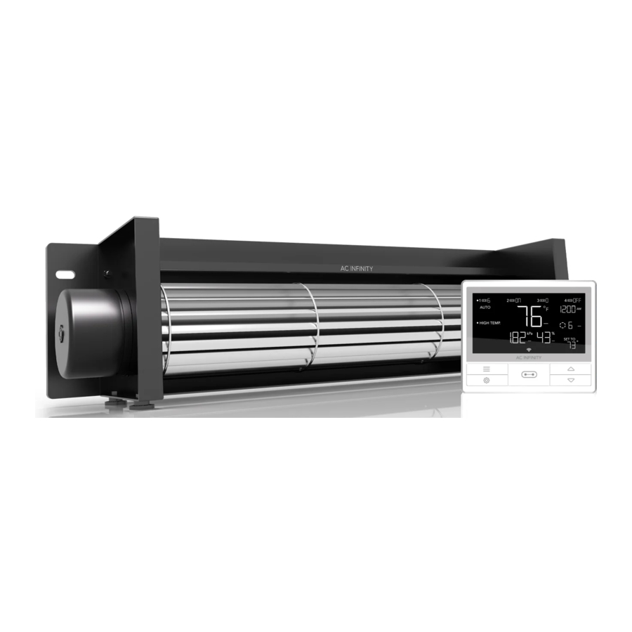
CONTROLLER 69 PRO
For in-depth programming instructions, refer to the included CONTROLLER 69 PRO Quick Start Guide. The following resources are also available for further assistance.
WEBPAGE OVERVIEW
Read through this instruction guide to easily explore all that your controller has to offer.

DOWNLOAD THE APP
THE AC INFINITY APP
- Download the AC Infinity app from the App Store or Play Store by searching "AC Infinity".
![play.google.com]()
![www.apple.com]()
- Open the AC Infinity app and follow the instructions to pair your controller with the app.
![]()


HOW TO USE THE APP
Visit our website at www.acinfinity.com or open your smartphone camera and scan the QR code below for more information on the AC Infinity app.

*Appearance and features subject to change.
ADD A DEVICE
BLUETOOTH
SETUP AND PAIRING
Power your device on before pairing your controller with the app. Logging in or creating an account beforehand will expedite the pairing process. Have your Wi-Fi network's name and password ready.
- Tap on the "+" tab to add your smart device.

- Select "Smart Controllers".


Wi-Fi and location permissions must be enabled on your mobile device before starting the pairing process.
- Select CONTROLLER 69 PRO.

- Hold the port button for 5 seconds to activate Bluetooth. Wait for the Bluetooth icon to start flashing on your controller's screen to release the button.

- Connect using Bluetooth. To connect using Wi-Fi, skip to step 8.

- Connecting with Bluetooth will disable Wi-Fi functionality. Go to the app settings page to re-enable and connect using Wi-Fi.


When pairing the app around multiple controllers, move your mobile device closer to your desired controller.
- Tap the DONE button to complete the pairing process.


WI-FI
- Repeat steps 1-5. Log in or create an account to continue.

- Enter your Wi-Fi network's password. You may also connect to an alternate 2.4 GHz router*.


When pairing the app around multiple controllers, move your mobile device closer to your desired controller.
- Follow these tips if the pairing process is unsuccessful.

- Tap the DONE button to complete the pairing process.


*This controller is only compatible with 2.4 GHz frequency band routers. When connecting using Wi-Fi, make sure your mobile device is not connected to a 5 GHz frequency band network.
- Your controller will appear in your smart device with a unique ID.


CONTROLLER 69 PRO FAQ
What devices are compatible with the CONTROLLER 69 PRO?
A: All AC Infinity devices that contain a UIS connector are compatible. If your AC Infinity device has a 4-pin Molex connector and an EC motor, it may still be compatible with the use of a UIS adapter to convert its connector to fit with the controller.
What does "level" refer to in the controller and app?
A: The level represents the intensity the device is running at. This is represented by a digit 0 to 10. Zero means the device is off, and 10 represents its running at its maximum. For fan devices, the level would be referring to their speed. For light devices, the level would be referring to its brightness. Note that on and off devices do not have a level setting.
Q: Why is my device is not turning off when the programming is triggering it to be off?
A: The figure set in OFF Mode determines the device's level when it's triggered to be OFF in all other modes. Set this figure to zero if you want the device to turn off when triggered OFF.
If this is occurring in AUTO Mode, check the points of your high and low triggers, which can all activate concurrently. Turn off any triggers that are not in use. If you are using the app, check to see if any ADVANCE programming is active, which can override any control programming.
Q: Why does my device not run or run at low levels when the programming is triggering it to be on?
A: The figure set in ON Mode determines the device's level when it's triggered to be ON in all other modes. Make sure this figure is not set to zero or the device will not run when triggered to be ON.
If this is occurring in AUTO Mode, check the points of your high and low triggers, which can all activate concurrently. Turn off any triggers that are not in use. If you are using the app, check to see if any ADVANCE programming is active, which can override any control programming.
Q: How do I stop my device from turning on and off too quickly in AUTO Mode?
A: The figure set in the TRANSITION under SETTINGS will determine how the device ramps up in levels when triggered to run in AUTO Mode. Set a transition threshold X. For every multiple of X that has surpassed your trigger point, the device will increase by one level. The lower the transition threshold is set to, the easier it will be for the device to ramp up in levels. If set to zero, the device will jump to the max set speed without ramping when triggered. This may cause the device to turn on and off quickly if the climate fluctuates back and forth. Increase the transition threshold number to help smooth out the transitions. Check the points of your high and low triggers, which can all activate concurrently. Turn off any triggers that are not in use.
Q: How do I set a minimum speed for constant ventilation, that would ramp up when triggered?
A: If a fan device is connected, the figure set in OFF Mode determines the fan speed when it's triggered to be OFF in all other modes. When the fan isn't triggered ON, it will be considered OFF and so it will run at that minimum speed continuously. Once triggered ON, it will change its speed to the figure set under ON Mode.
Q: Where is the best place to position the sensor probe?
A: Place the sensor probe as close as possible to the hottest or most humid spot in your space.
Q: Do I need to remove the plastic cap from the probe?
A: Yes. You will need to remove the plastic cap so the probe can accurately read climate conditions.
Q: Will I be able to use this controller with my own devices?
A: The CONTROLLER 69 PRO is only compatible with devices in the UIS ecosystem. Look for our logo on your AC Infinity device's packaging for UIS compatibility.
Q: Does the controller retain its settings after power is shut off?
A: Yes. If the controller's power is cut off and is powered on afterward, your settings will remain.
Q: My controller isn't pairing with the app. How do I fix this?
A: If the pairing process isn't successful, press any button to return to the normal screen. Then hold the port button for 5 seconds to try again. When starting the pairing process around multiple Wi-Fi controllers, move your smart device closer to the controller you wish to connect the app with.
Why does the app ask me for location permissions?
A: The app requires location permissions to find the relative position of your smart controller and communicate with existing Bluetooth devices already paired with the app. All Android devices prior to system version 12.0 will require location permissions to be turned on for the Bluetooth scan to be successful.
Q: Why do the port's level digits on the screen occasionally flash when I unplug a device?
A: The controller may have received electronic interference during the disconnection. To fix this, completely cut off power from the controller by unplugging all connected devices. Then plug them back into their previous ports and resume normal use.
AC INFINITY PRODUCTS
Register Booster Fans
The AIRTAP series is a line of register booster fans designed to quietly increase airflow coming from your central heat and air conditioning systems, increasing comfort for your home. Features a thermal controller with intelligent programming that will automatically adjust airflow strength in response to heating and cooling temperatures you have set.

Duct Fans
The CLOUDLINE series is a line of duct fans designed to quietly ventilate AV rooms and closets, as well as various DIY air circulation and exhaust projects. Features a thermal controller with intelligent programming that will automatically
adjust duct fan speeds in response to changing temperatures.

Crawlspace Fans
The AIRTITAN is a line of weather-proof fans designed to provide ventilation, odor, and moisture control for crawl spaces and basements. It features a digital controller with intelligent programming that will adjust airflow strength in response to high and low temperatures, as well as humidity.
Discover the latest innovations in environmental controls at acinfinity.com

PRODUCT WARNING


TO REDUCE THE RISK OF FIRE, ELECTRIC SHOCK, OR INJURY TO PERSONS, OBSERVE THE FOLLOWING:
- Ensure your power source conforms to the electrical requirements of this product.
- Check your local code restrictions for additional safety measures that may be needed for a proper code compliant installation.
- Read all instructions before installing and using this product.
- If you are unfamiliar or have doubts about performing this product's installation, seek the services of a qualified, trained, and licensed professional. Inappropriate installation will void this product's warranty.
- Do not attempt to hardwire this product. Performing any retrofitting actions may result in personal injury and/or electrical damage, and will void this product's warranty.
- This product must not be used in potentially hazardous locations such as flammable, explosive, chemical-laden, or wet atmospheres.
- Do not cover power cords with rugs or other fabric materials.
- This product has rotating parts. Safety precautions should be exercised during the installation, operation, and maintenance of this product.
- Do not insert or allow fingers or foreign objects to enter any ventilation or exhaust openings as it may cause electric shock, fire, or damage to this product. Do not block or tamper with this product in any manner while it is in operation.
- Do not depend on the on/off programming as the sole means of shutting power from this product. Unplug the power cord before installing, servicing, or moving this product.
- Do not operate this product while its cord is damaged, or if it malfunctions, has been dropped, or is damaged in any manner.
Documents / Resources
References
Download manual
Here you can download full pdf version of manual, it may contain additional safety instructions, warranty information, FCC rules, etc.
Download AC Infinity AIRBLAZE Series, AC-FBS10, AC-FBS12, AC-FBS14 - Blowers Manual
Advertisement


Need help?
Do you have a question about the AIRBLAZE Series and is the answer not in the manual?
Questions and answers