
Related Manuals for BETCO MOTOMOP


Summary of Contents for BETCO MOTOMOP
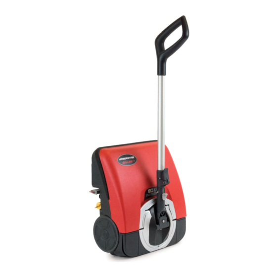
- Page 1 E84700-00 MOTOMOP ™ Small Area Cleaning Machine Operator and Parts Manual 1001 Brown Avenue • Toledo, Ohio 43607-0127 Customer Service: 888-GO-BETCO • Fax: 800-445-5056 • Technical Service: 877-856-5954 • www.betco.com...
-
Page 2: Table Of Contents
TABLE OF CONTENTS RECEIVING THE MACHINE ..........3 TECHNICAL INFORMATION..........4 GENERAL SAFETY INFORMATION ........ 5 MACHINE PREPARATION .........6 - 9 OPERATION ..............10 AFTER OPERATION ............11 MAINTENANCE .............12 - 14 DISPOSAL ..............15 MACHINE DIAGRAM AND PARTS LISTING ..16 - 35 WARRANTY .............. -
Page 3: Receiving The Machine
RECEIVING THE MACHINE Immediately check, when receiving the machine, that all the materials indicated on delivery documents have been received and also that the machine has not been damaged in transit. If it has been damaged, this damage must be immediately reported to the shipper and also to our customer’s service department or a claim may not be made. -
Page 4: Technical Information
TECHNICAL DESCRIPTION Measurement Unit MotoMop ™ Working width 13.5 Rear squeegee width Work capacity 7,320 Battery Lithium-ion Run time Up to 1 hour Brush diameter Brush motor Drive type Brush Assisted Maximum grade Vacuum motor Solution tank capacity 1/3 gallon... -
Page 5: General Safety Information
• Before using the machine, make sure that all covers are positioned as shown in this operating and maintenance manual. • When your BETCO machine is ready to be disposed of, the machine must be disposed of properly. It contains oils and elec- tronic components. -
Page 6: Machine Preparation
3. MACHINE ASSEMBLY 1. Take the package to the maintenance department. 2. Remove the MotoMop and all the accessories from the box. 3. Insert the lower tube (1) of the control handle into the hole on the joint (2) (Fig.1). -
Page 7: Machine Preparation
MACHINE PREPARATION 4. HANDLING AND TRANSPORTATION OF THE UNPACKED MACHINE The procedure for the safe handling of the machine is the following: 1. If the machine is in operation, turn it off via the main switch (1) (Fig.1). 2. Empty the recovery tank. 3. - Page 8 MACHINE PREPARATION 5. CHARGING THE BATTERY The battery must be charged prior to the first use, and when it is discharged from use. To recharge the battery, proceed as follows: 1. Take the machine to its battery recharging area. 2. If the machine is working, turn it off via the main switch (1) (Fig. 1). 3.
- Page 9 MACHINE PREPARATION 7. BATTERY MAINTENANCE AND DISPOSAL To power the MotoMop, use only the battery supplied in the package or supplied by a Betco authorized service provider. OTHER BATTERY TYPES CANNOT BE USED. The MotoMop is powered by a lithium-ion battery. The battery compartment can accommodate a single battery slot at 25.55V.
-
Page 10: Operation
OPERATION 1. Carry out the operations described in the “PREPARING TO WORK” chapter. 2. Check that the squeegee body is in contact with the surface to be cleaned. If it isn't, turn the knob (1) in the direction of the arrow (Fig.1). -
Page 11: After Operation
AFTER OPERATION Turn off the machine using the main switch (1) (Fig.1). Rotate the handle so it is vertical. Raise the squeegee off the floor and rotate the knob (2) in the direction of the arrow (Fig.2). Take the machine to the waste water drainage area. Remove the battery (3) from the machine. -
Page 12: Maintenance
MAINTENANCE Turn off the machine using the main switch (1) (Fig.1). Rotate the handle so it is vertical. Remove the battery (2) from the machine. To remove the battery, slide the stop lever (3) in the direction of the arrow (Fig.2). Remove the battery from the machine using the handle molded into (Fig.3). - Page 13 MAINTENANCE 25. Rotate the stop lever of the handle (20) in the direction of the arrow (Fig.22). 26. Collapse the handle, pushing the handle (21) towards the main part of the machine (Fig.23). 27. Rotate the clamp lever of the handle (20) in the direction of the arrow (Fig.24). 28.
- Page 14 MAINTENANCE Remove the filter cartridge supports (32) from the filter support (Fig.40). Remove the worn filter cartridge (31) from the filter cartridge support (32) and replace it with the new one (Fig.41). Repeat the operations in reverse order to reassemble all the parts. 38.
-
Page 15: Disposal
DISPOSAL To dispose of the machine, take it to a re-cycling center or an authorized collection center. Before scrapping the machine, it is necessary to remove and separate out the following materials, then send them to the appropriate collection centers in accordance with applicable environmental regulations: •... -
Page 16: Machine Diagram And Parts Listing
DIAGRAM 1 Diagram 8 Recovery Tank Diagram 5 Rear Cover Diagram 7 Solution Tank Diagram 3 Handle Assembly E84752 E84738 Diagram 6 Front Cover Diagram 9 Vacuum Assembly E22195 E84751 E84748 Diagram 10 Solution Delivery E84716 E84717 E84718 Diagram 4 Squeegee Assembly... - Page 17 DIAGRAM 1 PARTS LISTING Part # Description Qty. Part # Description Qty. E84738 LITHIUM ION BATTERY E84752 BATTERY CHARGER E84717 CYLINDRICAL BRUSH, BLUE, PPL 0.3 E22195 WASHER, FLAT M4 X 12 X 1 E84716 SCREW, PAN HEAD, PHIL SELF TAPPING M3.5 X 14 MM LG SS E84718 CYLINDRICAL BRUSH, BLACK, PPL 0.2 E84748...
- Page 18 DIAGRAM 2 MAIN BODY...
- Page 19 DIAGRAM 2 PARTS LISTING Part # Description Qty. Part # Description Qty. E84725 FILTER HOLDER E84706 BRUSH COVER ASSEMBLY E83702 WASHER, FENDER M6 X 24 MM X 2 MM E84726 VACUUM MOTOR COVER E84711 SCREW, SOCKET BUTTON HEAD M6 X 30 MM LG E84727 BATTERY RELEASE LEVER E82314...
- Page 20 DIAGRAM 3 HANDLE ASSEMBLY E84750 E84762 E84767 E84761 E84763 E81649 E84764 E83837 E84758 E84757 E84759 E84766 E81654 E84760 E84765...
- Page 21 DIAGRAM 3 PARTS LISTING Part # Description Qty. Part # Description Qty. E84756 LOCKING JOINT ASSEMBLY E84760 LOWER LOCKING LEVER E83837 SCREW, FLAT HEAD, PHIL M4 X 16 MM LG E84761 LEFT HANDLE SIDE E84762 RIGHT HANDLE SIDE E81649 NUT, HEX NYLOC M4 E84757 LOCKING HANDLE LEVER E84764...
- Page 22 DIAGRAM 4 SQEEGEE ASSEMBLY E81531 E84770 E81897 E81896 E84768 E81896 E84773 E22346 E81531 E84775 E81897 E84774 E84772 E84771 E84769 E22346 E84775 E84774...
- Page 23 DIAGRAM 4 PARTS LISTING Part # Description Qty. Part # Description Qty. E84770 SQUEEGEE SUPPORT BRACKET E81896 BOLT, CARRIAGE, M6 X 16 MM LG SS E81531 SQUEEGEE WHEEL E84771 SQUEEGEE MOUNTING BRACKET E22346 SQUEEGEE RETENTION PIN E84772 FRONT SQUEEGEE E81897 WHEEL BUSHING E84773 REAR SQUEEGEE...
- Page 24 DIAGRAM 5 REAR COVER E84777 E84788 E84794 E84781 E84789 E84776 E84788 E20705 E84808 E84795 E84794 E84790 E84781 E84787 E84791 E84784 E84792 E84787 E84751 E84750 E84779 E84780 E83935 E84785 E84783 E84782 E84796 E84793 E84750 E84750 E84750 E84778 E84797 E84798 E84750...
- Page 25 DIAGRAM 5 PARTS LISTING Part # Description Qty. Part # Description Qty. E84788 LIGHT DIFFUSER E84776 POWER ON/OFF BUTTON E84777 WATER PUMP ON/OFF E84789 CARRY HANDLE E84778 HANDLE POSTION SWITCH E84790 UPPER HANDLE PIVOT E84779 HANDLE PIVOT CIRCLIP E84791 HANDLE BUMPER E20705 NUT, NYLOC HEX M5 E84808...
- Page 26 DIAGRAM 6 FRONT COVER E84803 E84808 E84806 E84802 E82446 E84801 E84805 E84799 E84750 E84807 E84750 E84806 E84800 E82446 E84804 E84750...
- Page 27 DIAGRAM 6 PARTS LISTING Part # Description Qty. Part # Description Qty. E84799 RUBBER SCUFF GUARD E84804 LEFT LATCH HOUSING E82446 COVER LATCH SPRING E84805 RIGHT LATCH HOUSING E84806 COVER LATCH E84800 FRONT UPPER COVER E84801 FRONT LOWER COVER E84807 LED LENS E84802 FRONT BUMPER...
- Page 28 DIAGRAM 7 SOLUTION TANK E84817 E84816 E84205 E84810 E84815 E84812 E84813 E84811 E84750 E84814...
- Page 29 DIAGRAM 7 PARTS LISTING Part # Description Qty. Part # Description Qty. E84814 O-RING E84809 VALVE ASSEMBLY E84205 O-RING E84815 VALVE SPRING E84810 UPPER VALVE BODY E84817 RESERVOIR CAP E84811 LOWER VALVE BODY E84816 SOLUTION TANK E84812 VALVE PLUNGER E84750 SCREW, PAN HEAD, PHIL SELF TAPPING M3 X 10 MM LG SS 2 E84813 O-RING...
- Page 30 DIAGRAM 8 RECOVERY TANK E84750 E84825 E84822 E84821 E84750 E84820 E84824 E84823 E84819...
- Page 31 DIAGRAM 8 PARTS LISTING Part # Description Qty. Part # Description Qty. E84825 UPPER RECOVERY TANK COVER E84818 RECOVERY TANK COVER ASSEMBLY E84819 V-RING GASKET E84750 SCREW, PAN HEAD, PHIL SELF TAPPING M3 X 10 MM LG SS 9 E84820 HANDLE PIVOT INSERT E84826 FLOAT...
- Page 32 DIAGRAM 9 VACUUM ASSEMBLY E84828 E84829 E84828 E84829 E83935 E84833 E84834 E84819 E84769 E84750 E84832 E84819 E84831 E84830...
- Page 33 DIAGRAM 9 PARTS LISTING Part # Description Qty. Part # Description Qty. E84830 VACUUM HOSE E84827 VACUUM MOTOR ASSEMBLY, 24V 100W E84828 ELECTRICAL CONNECTER COVER E84769 V-RING GASKET E83935 WIRE TIE E84831 V-RING GASKET E84829 ELECTRICAL CONNECTER E84832 VACUUM MANIFOLD E84833 VACUUM MOTOR ONLY, 24V 100W E84750...
- Page 34 DIAGRAM 10 SOLUTION DELIVERY E84840 E84708 E84841 E84836 E84750 E84750 E84842 E84839 E84835 E84843 E84708 E84750 E84750 E84837 E84838 E84835 E84835 E84843...
- Page 35 DIAGRAM 10 PARTS LISTING Part # Description Qty. Part # Description Qty. E84840 REAR PUMP MOUNT E84835 SILICONE HOSE, 7OD X 4ID X 225L E84836 SILICONE HOSE, 7OD X 4ID X 350L E84841 SOLUTION PUMP E84708 WASHER, FFENDER, M3 X 12 X 0.8 ZINC E84842 SOLUTION HOSE T-FITTING E84837...
-
Page 36: Warranty
Service Distributor. If the original part is returned within the warranty policy period from date of delivery for inspection by Betco and is found to be defective the owner will be credited for the cost of replacement parts plus shipping and handling.
Need help?
Do you have a question about the MOTOMOP and is the answer not in the manual?
Questions and answers