Table of Contents
Advertisement
Quick Links
Advertisement
Table of Contents

Subscribe to Our Youtube Channel
Related Manuals for AIREDALE ET05D


Summary of Contents for AIREDALE ET05D
- Page 1 Ecotel Outdoor ™ Downflow Telecom Unit 5-15kW R410A Technical Manual...
- Page 2 Airedale Ltd. endeavours to ensure that the information in this document is correct and fairly stated, but none of the statements are to be relied upon as a statement or representation of fact. Airedale Ltd. does not accept liability for any error or omission, or for any reliance placed on the information contained in this document.
- Page 3 Remember do not perform a lift that exceeds your ability. Refrigerant Warning The Airedale unit uses R410A refrigerant which requires careful attention to proper storage and handling procedures. Use only manifold gauge sets designed for use with R410A refrigerant. Use only refrigerant recovery units and cylinders designed for high pressure refrigerants.
-
Page 4: Environmental Policy
● Measure, control and verify environmental performance through internal and external audits ● Continually improve our environmental performance CE Directive Airedale certify that the equipment detailed in this manual conforms with the following EC Directives: Electromagnetic Compatibility Directive (EMC) 2014/30/EU... -
Page 5: Table Of Contents
Telecoms Ecotel™ Contents Environmental Policy Specifier’s Guide Nomenclature Introduction System Configurations Unit Overview Case Sizes Operating Limits Refrigeration Components Airflow Components Electrical Controls External Installation Data Lifting/Positioning Installation Electrical Product Application Dimensions Cabin Mount and Incoming Services Detail Pipework Schematics Interconnecting Wiring pLAN Termination Ecotel™... - Page 6 Ecotel™ Telecoms Technical Data Free Cooling Performance Data Sound Measurement Technical Data - 400V 50Hz Performance Data ET05D ET08D ET12D ET15D Technical Data - 230V 50Hz Performance Data ET05D ET08D ET12D ET15D Technical Data - 380V 60Hz Performance Data ET12D...
-
Page 7: Specifier's Guide
Telecoms Ecotel™ Specifier’s Guide Nomenclature EcoTel Unit 05-15 Nominal cooling capacity in kW Downflow Separator High Efficiency DX Cooling Single Circuit, Single Compressor Dual Circuit, Single Compressor Free Cooling No Emergency Backup Emergency Backup (-48VDC) Separator 400V / 3PH + N / 50Hz 230V / 1PH + N / 50Hz 380V / 3PH + N / 60Hz 220V / 3PH / 60Hz... - Page 8 Ecotel™ Telecoms The Ecotel 5-15kW range shall offer the following: Standard features: ● Fresh air free cooling ability with 100% mechanical backup and concurrent cooling stage ● R410A refrigerant ● Fixed speed scroll compressors ● Efficient EC evaporator fans ● Cost effective AC condenser fan ●...
-
Page 9: System Configurations
Telecoms Ecotel™ System Configurations Mechanical Cooling Mode When the ambient temperature is above the set point of the cabin space, the fresh air damper switches into the vertical position and cycles the cabin air through the unit and evaporator coil. The mechanical circuit is switched on providing 100% mechanical cooling. - Page 10 Ecotel™ Telecoms Concurrent Mode When the ambient temperature is below the set point of the cabin space, but not low enough to provide full free cooling duty, the unit can cycle the compressor on and off to cool the ambient fresh air and provide the required cooling duty, whilst saving energy by the unit not being in full mechanical cooling mode.
- Page 11 Telecoms Ecotel™ Attend Mode Attend mode is intended for situations where it is necessary for an engineer to work inside the cabin. Attend mode is activated by pressing the attend button on entry to the cabin. In attend mode, the temperature setpoint within the cabin will be changed to attend setpoint, and the evaporator fan speed will be limited.
-
Page 12: Unit Overview
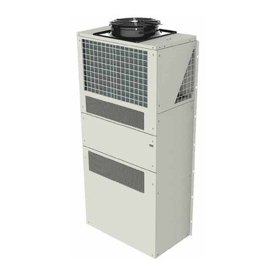
Ecotel™ Telecoms Unit Overview Features 450mm AC Axial Condenser RAL 7038 (Agate Gray) or Fan (ErP compliant) RAL 6014 (Yellow Olive) painted panels Condenser Coil protected by punched panels. “V” block coil for increased surface area Exhaust Louvre Tamper Proof Fixings Inlet Louvre Control Panel Access Return Air Aperture... -
Page 13: Case Sizes
Telecoms Ecotel™ Case Sizes The Ecotel 5-15kW range has a total of two case sizes. The 5kW & 8kW units shall utilise the same case dimensions, as shall the 12kW & 15kW units, which results in two case widths. The unit depth remains constant throughout the range. The difference in capacities shall be dependent on component sizing within the unit case. -
Page 14: Refrigeration Components
Ecotel™ Telecoms Refrigeration Components Evaporator Coil Fixed Speed Scroll Compressor System Configuration Features ET05/08D-HX ET12/15D-HX ● ● Fixed Speed Scroll Compressor ● ● Hydrophilic Coated Evaporator Coil ● ● Condenser Coil ○ ○ Epoxy Coated Condenser Coil ● ● Electronic Expansion Valves (EEV) ○... - Page 15 Telecoms Ecotel™ Electronic Expansion Valves (EEV) Electronic expansion valves differ to the normal thermostatic expansion valves in their ability to maintain control of the suction superheat at reduced head pressures. This can lead to significant energy savings particularly at reduced loading and low ambient temperatures. EEV step position, superheat setpoint, head pressure set point and other features can be viewed and adjusted via the microcontroller display.
-
Page 16: Airflow Components
Ecotel™ Telecoms Airflow Components EC Centrifugal Fan Spring Return Air Damper Actuator Fire Rated Damper System Configuration Features ET05/08D-HX ET12/15D-HX ● ● EC Centrifugal Evaporator Fans ○ ○ Upgraded EC Centrifugal Evaporator Fans ○ ○ -48VDC Centrifugal Evaporator Fans ● ●... - Page 17 Telecoms Ecotel™ Electronically Commutated (EC) Fan Motor EC motors incorporate integrated electronics to convert AC power to DC for efficient and accurate speed control and are adjustable via the microprocessor display keypad. The fans offer maximum air flow performance while keeping sound levels to a minimum. This gives the flexibility of connecting to AC mains with the efficiency and simple speed control of a DC motor.
-
Page 18: Electrical
Ecotel™ Telecoms Electrical Condenser Fan Unit Circuit Heating Speed Controller Breakers Contactor Controller Compressor Differential Pressure Sensor Differential Pressure Switch Soft Starter System Configuration Features ET05/08D-HX ET12/15D-HX ● ● Mains Isolator ○ ○ Compressor Soft Start ○ ○ -48VDC Emergency Back-Up Supply ○... - Page 19 Telecoms Ecotel™ Electrical Image shows typical isolator placement. For illustration purposes only. Mains Isolator To comply with BS EN 6024-1:2006 Safety of Machinery – Electrical Equipment Machines, each unit shall have an accompanying isolator (switch disconnecting device). The supply disconnecting device shall isolate the electrical equipment of the telecoms unit from the electrical supply when required.
- Page 20 The table below outlines which voltages are available for each unit configuration: Unit Voltage Unit 400V/3PH/50Hz (-0) 230V/1PH/50Hz (-7) 380v/3PH/60Hz (-1) 220V /3PH/60Hz (-2) ● ● — — ET05D-_X1F_-_ ● ● ● — ET08D-_X1F_-_ ● ● ● ● ET12D-_X1F_-_ ●...
-
Page 21: Controls
Telecoms Ecotel™ Controls pGD1 Display pCO OEM+ controller System Configuration Features ET05/08D-HX ET12/15D-HX ● ● pC0 OEM+ Controller ● ● pGD1 Remote Display ● ● Evaporator Fan Control ● ● Return Air Temperature Control ○ ○ Constant air Volume ○ ○... - Page 22 Ecotel™ Telecoms Display/Keypad The display keypad features a simple array of keys to navigate through the in-built menus. With an 8 x 22 character (132 x 64 pixel) screen size, back lit in white for improved contrast, the larger screen shall provide for user friendly viewing and easy status recognition by displaying a combination of text and icons.
- Page 23 Telecoms Ecotel™ Display Icons To ensure the software is easy to read at a glance, the Ecotel Mk4 user interface is largely graphical, containing a large number of icons to represent different modes, actions or components. The following table is a glossary of icons to use as a reference: Icon Name/Description Used To Represent...
-
Page 24: Alarm Display
For further details, please contact Airedale Controls. BMS Interface Cards BMS Interface Card controlled units can be interfaced with most BMS which are factory fitted, please contact Airedale for more information. A wide range of protocols shall be accommodated through the use of interface devices. Available as a standard option are: ModBus/Jbus, and Carel. -
Page 25: External
For specific markets units shall be shipped, mounted on wooden pallet and covered with polythene. The pallet shall be mechanically fixed to the unit for transportation only (Please contact Airedale for this option). Add 50mm to depth and width, 160mm to height. -
Page 26: Installation Data
● Remove packing and check that the unit is exactly as ordered. Any discrepancy to order, or transit damage, should be reported to Airedale immediately. ● Airedale recommends that whenever possible, the packaging is left covering the unit, to protect it from damage and general site debris. -
Page 27: Product Application
Telecoms Ecotel™ Installation Data Product Application CABIN MOUNTING TEMPLATE CAUTION Units must be supported by a 3 inch cabin mounted angle iron (not supplied). ET12/15D-HX*F*-* on a 3m tall cabin Ecotel™ 5-15kW Technical Manual 9321381 V1.3.0 02_2018... -
Page 28: Dimensions
Ecotel™ Telecoms Installation Data Dimensions ET05/08D-HX1F*-* Ecotel™ 5-15kW Technical Manual 9321381 V1.3.0 02_2018... - Page 29 Telecoms Ecotel™ Installation Data Dimensions ET12/15D-HX1F*-* Ecotel™ 5-15kW Technical Manual 9321381 V1.3.0 02_2018...
-
Page 30: Cabin Mount And Incoming Services Detail
Ecotel™ Telecoms Installation Data ET05/08D-HX1F*-* Cabin Mount and Incoming Services Detail Internal View INCOMING SERVICES DETAIL FLOOR LEVEL MIN DISTANCE FROM FLOOR Fire damper and deflection grilles are to be located centrally around the cut-outs and secured using tamper proof fixings. Cabin Mounting External View 14 Off cabin mounting holes ‘A’... - Page 31 Telecoms Ecotel™ Installation Data ET12/15D-HX1F*-* Cabin Mount and Incoming Services Detail Internal View INCOMING SERVICES DETAIL FLOOR LEVEL MIN DISTANCE FROM FLOOR Fire damper and deflection grilles are to be located centrally around the cut-outs and secured using tamper proof fixings. Cabin Mounting External View 1054...
-
Page 32: Pipework Schematics
Ecotel™ Telecoms Installation Data Pipework Schematics Single Circuit Condenser Coil 5/16” Discharge Line Liquid Line 5/16” Circuit 1 - DX Liquid Expansion Line 5/16” Evaporator Coil Suction Line 5/16” Key: All Items R410A 5/16” Schrader Valve 5/16” Scroll Compressor Electronic Expansion Valve Low Pressure Switch High Pressure Switch Sight Glass... - Page 33 Telecoms Ecotel™ Installation Data Pipework Schematics Dual Circuit Interlaced Condenser Coil 5/16” Liquid Line Discharge Line 5/16” 5/16” 5/16” Circuit 2 - DX Circuit 1 - DX Liquid Expansion Line 5/16” 5/16” Interlaced Evaporator Coil 5/16” Suction Line 5/16” Key: All Items R410A 5/16”...
-
Page 34: Interconnecting Wiring
Ecotel™ Telecoms Installation Data Interconnecting Wiring Power Connections ç ç Mains Incoming Supply (400V / 3PH / + N / 50Hz or ç 380V / 3PH / + N / 60Hz) ç ç ç Indoor Unit ç Mains Incoming Supply (220V / 3PH / 60Hz) ç... -
Page 35: Plan Termination
Telecoms Ecotel™ pLAN Termination pLAN Termination The plugged termination ensures that the connections are made simultaneously. Failure to attach the cables this way may cause damage to the controller. Customer Side RxTx - RxTx + RxTx - RxTx + Panel Side Ecotel™... -
Page 36: Technical Data
Ecotel™ Telecoms Technical Data Free Cooling Performance Data Standard EC Fans ET05D-HX1F0-* R.A.T @ 35°C R.A.T @ 25°C R.A.T @ 30°C Ambient Temperature (°C) R.A.T @ 25°C R.A.T @ 30°C R.A.T @ 35°C Upgraded EC Fans ET05D-HX1F0-* R.A.T @ 35°C R.A.T @ 25°C... - Page 37 Telecoms Ecotel™ Technical Data Free Cooling Performance Data Standard EC Fans ET08D-HX1F0-* R.A.T @ 35°C R.A.T @ 30°C R.A.T @ 25°C Ambient Temperature (°C) R.A.T @ 25°C R.A.T @ 30°C R.A.T @ 35°C Upgraded EC Fans ET08D-HX1F0-* R.A.T @ 35°C R.A.T @ 25°C R.A.T @ 30°C Ambient Temperature (°C)
- Page 38 Ecotel™ Telecoms Technical Data Free Cooling Performance Data Standard EC Fans ET12/15D-HX1F0-* R.A.T @ 35°C R.A.T @ 30°C R.A.T @ 25°C Ambient Temperature (°C) R.A.T @ 25°C R.A.T @ 30°C R.A.T @ 35°C Upgraded EC Fans ET12/15D-HX1F0-* R.A.T @ 35°C R.A.T @ 30°C R.A.T @ 25°C Ambient Temperature (°C)
-
Page 39: Sound Measurement
3dB(A) for each side added. The below data is based on unit typical running conditions. Nominal Operation (dBA) Sound Measurement Free Cooling Power Pressure @ 1m ET05D-HX1F*-* Pressure @ 3m Pressure @ 10m Power Pressure @ 1m ET08D-HX1F*-* Pressure @ 3m... -
Page 40: Technical Data - 400V 50Hz
Ambient °C Air On °C / %RH TC (kW) SC (kW) TC (kW) SC (kW) TC (kW) SC (kW) TC (kW) SC (kW) TC (kW) SC (kW) 28°C 33.7% 30°C 30% ET05D-HX1F0-0 32°C 26.8% 28°C 33.7% 30°C 30% ET05D-HX1F1-0 32°C 26.8% 28°C 33.7%... - Page 41 Telecoms Ecotel™ Intentionally Blank Ecotel™ 5-15kW Technical Manual 9321381 V1.3.0 02_2018...
-
Page 42: Et05D
Ecotel™ Telecoms Technical Data - 400V 50Hz ET05D Mechanical Data ET05D-HX1F1-0 ET05D-HX1F0-0 Capacity - DX Cooling 6.09 6.09 Gross Total 6.09 6.09 Gross Sensible 2.88 2.86 Capacity Steps Capacity - Free Cooling 5.25 6.59 Gross Total m³/s 0.43 0.55 Max Airflow... - Page 43 Telecoms Ecotel™ Technical Data - 400V 50Hz ET05D Electrical Data ET05D-HX1F0-0 ET05D-HX1F1-0 Electrical Supply Data 400 / 3PH + N / 50Hz 400 / 3PH + N / 50Hz Mains Supply 48VDC Clients Backup Power Supply 24VAC 24VDC Controls Circuit mm²...
-
Page 44: Et08D
Ecotel™ Telecoms Technical Data - 400V 50Hz ET08D Mechanical Data ET08D-HX1F0-0 ET08D-HX1F1-0 Capacity - DX Cooling Gross Total Gross Sensible 2.93 2.93 Capacity Steps Capacity - Free Cooling 8.82 7.02 Gross Total m³/s 0.73 0.58 Max Airflow Dimensions 910 x 580 x 2018 W x D x H Weights Machine... - Page 45 Telecoms Ecotel™ Technical Data - 400V 50Hz ET08D Electrical Data ET08D-HX1F0-0 ET08D-HX1F1-0 Electrical Supply Data 400 / 3PH + N / 50Hz 400 / 3PH + N / 50Hz Mains Supply 48VDC Clients Backup Power Supply 24VAC 24VDC Controls Circuit mm²...
-
Page 46: Et12D
Ecotel™ Telecoms Technical Data - 400V 50Hz ET12D Mechanical Data ET12D-HX1F0-0 ET12D-HX1F1-0 ET12D-HX2F0-0 ET12D-HX2F1-0 Capacity - DX Cooling 12.3 12.3 13.14 13.14 Gross Total 12.3 12.3 13.14 13.14 Gross Sensible 3.41 3.28 3.03 2.94 Capacity Steps Capacity - Free Cooling 12.36 10.24 12.36... - Page 47 Telecoms Ecotel™ Technical Data - 400V 50Hz ET12D Electrical Data ET12D-HX1F0-0 ET12D-HX1F1-0 ET12D-HX2F0-0 ET12D-HX2F1-0 Electrical Supply Data 400 / 3PH + 400 / 3PH + 400 / 3PH + 400 / 3PH + Mains Supply N / 50Hz N / 50Hz N / 50Hz N / 50Hz 48VDC...
-
Page 48: Et15D
Ecotel™ Telecoms Technical Data - 400V 50Hz ET15D Mechanical Data ET15D-HX1F0-0 ET15D-HX1F1-0 ET15D-HX2F0-0 ET15D-HX2F1-0 Capacity - DX Cooling 14.84 14.84 15.28 15.28 Gross Total 14.84 14.84 15.28 15.28 Gross Sensible 3.11 2.99 2.84 2.74 Capacity Steps Capacity - Free Cooling 12.41 10.28 12.41... - Page 49 Telecoms Ecotel™ Technical Data - 400V 50Hz ET15D Electrical Data ET15D-HX1F0-0 ET15D-HX1F1-0 ET15D-HX2F0-0 ET15D-HX2F1-0 Electrical Supply Data 400 / 3PH + 400 / 3PH + 400 / 3PH + 400 / 3PH + Mains Supply N / 50Hz N / 50Hz N / 50Hz N / 50Hz 48VDC...
-
Page 50: Technical Data - 230V 50Hz
Ambient °C Air On °C / %RH TC (kW) SC (kW) TC (kW) SC (kW) TC (kW) SC (kW) TC (kW) SC (kW) TC (kW) SC (kW) 28°C 33.7% 30°C 30% ET05D-HX1F0-7 32°C 26.8% 28°C 33.7% 30°C 30% ET05D-HX1F1-7 32°C 26.8% 28°C 33.7%... - Page 51 Telecoms Ecotel™ Intentionally Blank Ecotel™ 5-15kW Technical Manual 9321381 V1.3.0 02_2018...
-
Page 52: Et05D
Ecotel™ Telecoms Technical Data - 230V 50Hz ET05D Mechanical Data ET05D-HX1F0-7 ET05D-HX1F1-7 Capacity - DX Cooling 6.15 6.15 Gross Total 6.15 6.15 Gross Sensible 2.91 2.89 Capacity Steps Capacity - Free Cooling 5.25 6.59 Gross Total m³/s 0.43 0.55 Max Airflow... - Page 53 Telecoms Ecotel™ Technical Data - 230V 50Hz ET05D Electrical Data ET05D-HX1F0-7 ET05D-HX1F1-7 Electrical Supply Data 230 / 1PH + N / 50Hz 230 / 1PH + N / 50Hz Mains Supply 48VDC Clients Backup Power Supply 24VAC 24VDC Controls Circuit mm²...
-
Page 54: Et08D
Ecotel™ Telecoms Technical Data - 230V 50Hz ET08D Mechanical Data ET08D-HX1F0-7 ET08D-HX1F1-7 Capacity - DX Cooling 8.44 8.44 Gross Total 8.44 8.44 Gross Sensible 2.92 2.93 Capacity Steps Capacity - Free Cooling 8.82 7.02 Gross Total m³/s 0.73 0.58 Max Airflow Dimensions 910 x 580 x 2018 W x D x H... - Page 55 Telecoms Ecotel™ Technical Data - 230V 50Hz ET08D Electrical Data ET08D-HX1F0-7 ET08D-HX1F1-7 Electrical Supply Data 230 / 1PH + N / 50Hz 230 / 1PH + N / 50Hz Mains Supply 48VDC Clients Backup Power Supply 24VAC 24VDC Controls Circuit mm²...
-
Page 56: Et12D
Ecotel™ Telecoms Technical Data - 230V 50Hz ET12D Mechanical Data ET12D-HX1F0-7 ET12D-HX1F1-7 ET12D-HX2F0-7 ET12D-HX2F1-7 Capacity - DX Cooling 12.4 12.4 13.33 13.33 Gross Total 12.4 12.4 13.33 13.33 Gross Sensible 3.31 3.11 3.01 Capacity Steps Capacity - Free Cooling 12.36 10.24 12.36 10.24... - Page 57 Telecoms Ecotel™ Technical Data - 230V 50Hz ET12D Electrical Data ET12D-HX1F0-7 ET12D-HX1F1-7 ET12D-HX2F0-7 ET11D-HX2F1-7 Electrical Supply Data 230 / 1PH + 230 / 1PH + 230 / 1PH + 230 / 1PH + Mains Supply N / 50Hz N / 50Hz N / 50Hz N / 50Hz 48VDC...
-
Page 58: Et15D
Ecotel™ Telecoms Technical Data - 230V 50Hz ET15D Mechanical Data ET15D-HX1F0-7 ET15D-HX1F1-7 ET15D-HX2F0-7 ET15D-HX2F1-7 Capacity - DX Cooling 14.85 14.85 15.39 15.39 Gross Total 14.85 14.85 15.39 15.39 Gross Sensible 3.07 2.94 2.79 Capacity Steps Capacity - Free Cooling 12.41 10.28 12.41 10.28... - Page 59 Telecoms Ecotel™ Technical Data - 230V 50Hz ET15D Electrical Data ET15D-HX1F0-7 ET15D-HX1F1-7 ET15D-HX2F0-7 ET15D-HX2F1-7 Electrical Supply Data 230 / 1PH + 230 / 1PH + 230 / 1PH + 230 / 1PH + Mains Supply N / 50Hz N / 50Hz N / 50Hz N / 50Hz 48VDC...
-
Page 60: Technical Data - 380V 60Hz
Ecotel™ Telecoms Technical Data - 380V 60Hz Performance Data Ambient °C Air On °C / %RH TC (kW) SC (kW) TC (kW) SC (kW) TC (kW) SC (kW) TC (kW) SC (kW) TC (kW) SC (kW) 28°C 33.7% 11.8 11.8 11.6 11.6 11.2... - Page 61 Telecoms Ecotel™ Intentionally Blank Ecotel™ 5-15kW Technical Manual 9321381 V1.3.0 02_2018...
-
Page 62: Et12D
Ecotel™ Telecoms Technical Data - 380V 60Hz ET12D Mechanical Data ET12D-HX1F1-1 ET12D-HX1F0-1 Capacity - DX Cooling 11.81 11.81 Gross Total 11.81 11.81 Gross Sensible 2.62 Capacity Steps Capacity - Free Cooling 12.36 10.24 Gross Total m³/s 1.02 0.85 Max Airflow Dimensions 1020 x 580 x 2168 W x D x H... - Page 63 Telecoms Ecotel™ Technical Data - 380V 60Hz ET12D Electrical Data ET12D-HX1F0-1 ET12D-HX1F1-1 Electrical Supply Data 380 / 3PH + N / 60Hz 380 / 3PH + N / 60Hz Mains Supply 48VDC Clients Backup Power Supply 24VAC 24VDC Controls Circuit mm²...
-
Page 64: Et15D
Ecotel™ Telecoms Technical Data - 380V 60Hz ET15D Mechanical Data ET15D-HX1F0-1 ET15D-HX1F1-1 ET15D-HX2F0-1 ET15D-HX2F1-1 Capacity - DX Cooling 14.97 14.97 14.76 14.76 Gross Total 14.97 14.97 14.76 14.76 Gross Sensible 2.45 2.37 2.37 Capacity Steps Capacity - Free Cooling 12.41 10.28 12.41 10.28... - Page 65 Telecoms Ecotel™ Technical Data - 380V 60Hz ET15D Electrical Data ET15D-HX1F0-1 ET15D-HX1F1-1 ET15D-HX2F0-1 ET15D-HX2F1-1 Electrical Supply Data 380 / 3PH + 380 / 3PH + 380 / 3PH + 380 / 3PH + Mains Supply N / 60Hz N / 60Hz N / 60Hz N / 60Hz 48VDC...
-
Page 66: Technical Data - 220V 60Hz
Ecotel™ Telecoms Technical Data - 220V 60Hz Performance Data Ambient °C Air On °C / %RH TC (kW) SC (kW) TC (kW) SC (kW) TC (kW) SC (kW) TC (kW) SC (kW) TC (kW) SC (kW) 28°C 33.7% 30°C 30% ET08D-HX1F0-2 32°C 26.8% 28°C 33.7%... - Page 67 Telecoms Ecotel™ Intentionally Blank Ecotel™ 5-15kW Technical Manual 9321381 V1.3.0 02_2018...
-
Page 68: Et08D
Ecotel™ Telecoms Technical Data - 220V 60Hz ET08D Mechanical Data ET08D-HX1F1-2 ET08D-HX1F0-2 Capacity - DX Cooling 8.24 8.24 Gross Total 8.24 8.24 Gross Sensible 2.39 2.39 Capacity Steps Capacity - Free Cooling 8.82 7.02 Gross Total m³/s 0.73 0.58 Max Airflow Dimensions 910 x 580 x 2018 W x D x H... - Page 69 Telecoms Ecotel™ Technical Data - 220V 60Hz ET08D Electrical Data ET08D-HX1F0-2 ET08D-HX1F1-2 Electrical Supply Data 220 / 3PH / 60Hz 220 / 3PH / 60Hz Mains Supply 48VDC Clients Backup Power Supply 24VAC 24VDC Controls Circuit mm² Maximum Mains Incoming Cable Size Mechanical Cooling - ARI (AC) 12.73 13.53...
-
Page 70: Et12D
Ecotel™ Telecoms Technical Data - 220V 60Hz ET12D Mechanical Data ET12D-HX1F1-2 ET12D-HX1F0-2 Capacity - DX Cooling 12.42 12.42 Gross Total 12.42 12.42 Gross Sensible 2.62 Capacity Steps Capacity - Free Cooling 12.36 10.24 Gross Total m³/s 1.02 0.85 Max Airflow Dimensions 1020 x 580 x 2168 W x D x H... - Page 71 Telecoms Ecotel™ Technical Data - 220V 60Hz ET12D Electrical Data ET12D-HX1F0-2 ET12D-HX1F1-2 Electrical Supply Data 220 / 3PH / 60Hz 220 / 3PH / 60Hz Mains Supply 48VDC Clients Backup Power Supply 24VAC 24VDC Controls Circuit mm² Maximum Mains Incoming Cable Size Mechanical Cooling - ARI (AC) 20.05 18.65...
-
Page 72: Et15D
Ecotel™ Telecoms Technical Data - 220V 60Hz ET15D Mechanical Data ET15D-HX1F1-2 ET15D-HX1F0-2 Capacity - DX Cooling 14.05 14.05 Gross Total 14.05 14.05 Gross Sensible 2.54 2.46 Capacity Steps Capacity - Free Cooling 12.41 10.28 Gross Total m³/s 1.03 0.85 Max Airflow Dimensions 1020 x 580 x 2168 W x D x H... - Page 73 Telecoms Ecotel™ Technical Data - 220V 60Hz ET15D Electrical Data ET15D-HX1F0-2 ET15D-HX1F1-2 Electrical Supply Data 220 / 3PH / 60Hz 220 / 3PH / 60Hz Mains Supply 48VDC Clients Backup Power Supply 24VAC 24VDC Controls Circuit mm² Maximum Mains Incoming Cable Size Mechanical Cooling - ARI (AC) 22.27 20.87...
-
Page 74: Commissioning
Ecotel™ Telecoms Commissioning Each Ecotel Outdoor unit leaves Airedale’s manufacturing facility fully charged and pre-commissioned. Pre Start Checks Once the whole system has been installed it is most important that the following pre-start checks are made: ● The equipment is exactly as ordered. -
Page 75: Full Free Cooling
Telecoms Ecotel™ Commissioning Full Free Cooling When the ambient is low enough and free cooling can totally satisfy the cooling requirement of the exchange, the damper will open and the fan will modulate to maintain the design room set point. On low supply temperatures, the damper will modulate closed. -
Page 76: Maintenance
Ecotel™ Telecoms Maintenance Owner’s Responsibility It is the owner’s responsibility to ensure that the unit can be maintained correctly ensure the following requirements are met, and maintain a safe working environment around the unit, free from obstructions and debris. The unit shall adhere to the following maintenance regime as a minimum. The equipment contains live electrical and moving parts, ISOLATE prior to maintenance or repair CAUTION work. -
Page 77: General Inspections
Telecoms Ecotel™ Maintenance General Inspections Task Frequency 3 Mths 12 Mths 60 Mths Check for visible mechanical damage to unit. ● Visually inspect the unit for general wear and tear, treat metalwork. ● General Rust should be inhibited, primed and Inspections ●... -
Page 78: Electrical Inspections
Ecotel™ Telecoms Maintenance Electrical Inspections Task Frequency 3 Mths 12 Mths 60 Mths ● Check main power supply voltages ● Check electrical terminals are tight. ● Check for signs of hot spots/discolouration on power cables. Electrical Inspections ● Check operation of electric trace heating ●... -
Page 79: Controls
Telecoms Ecotel™ Maintenance Controls Task Frequency 3 Mths 12 Mths 60 Mths ● Controls Change controller battery.* Service Tools/Test Equipment Safety Equipment • Small Terminal Screwdriver • Electrostatic Wristband *The controller will keep the strategy for a short period of time with no battery. Procedures The following controller settings are to be recorded on the maintenance sheet: ●... -
Page 80: Troubleshooting
Ecotel™ Telecoms Troubleshooting FAULT POSSIBLE CAUSE REMEDY/ACTION Unit not operating - Power Off. Main/local isolator off Check all isolators from mains to unit. Check all mains fuses. Replace after Mains Fuse(s) failed. correcting fault. Check for loose wire. Unit not operating - Check volt free contacts, investigate and Power On. - Page 81 Telecoms Ecotel™ Troubleshooting FAULT POSSIBLE CAUSE REMEDY/ACTION High room temperature Damper jammed in free cooling position Damper not operating correctly during high ambient conditions. Compressor(s) not operating. See unit not operating power off - power on. Important: Check electrical phase rotation. Compressor(s) not operating efficiently.
- Page 82 Ecotel™ Telecoms Troubleshooting Noisy compressor. Start-up: Brief period of mechanical No detrimental effect - no action necessary. noise may be noticed on start up due to initial contacting of the spirals. This will quickly disappear. Shut down: Compressor reverses No detrimental effect - no action necessary. momentarily as internal pressure equalises.
-
Page 83: Alarms
Telecoms Ecotel™ Alarms Alarm Menu Display Alarm number Alarm name Alarm Status Time Date Alarm Log The alarm page offers a log of the last 150 alarm messages in a scrolling log, pressing the alarm button will enter the alarm page. Consequently the most recent alarm has the lowest log number (001) and will be displayed upon entering the alarm page. - Page 84 Ecotel™ Telecoms Alarms The following lists display all alarms available in the Ecotel Mk4. Some of these alarms may not be available depending on unit type and selected options. Code Name Description Action Reset Importance Power Restart Mains power restarted For information Non-Critical Critical...
- Page 85 Telecoms Ecotel™ Alarms Code Name Description Action Reset Importance Compressor 2 MCB Trip Compressor 2 MCB is open circuit Disable circuit 2 Circuit 1 Low Pressure Low suction pressure circuit 1 Disable circuit 1 Trip Circuit 2 Low Pressure Low suction pressure circuit 2 Disable circuit 2 Auto Trip...
- Page 86 Ecotel™ Telecoms Alarms Code Name Description Action Reset Importance Expansion Valve Driver Probe reading error on Probe Failure expansion valve driver Expansion Valve Driver Low superheat value on Low Superheat circuit 1 or 2 Disable affected Auto Critical circuit Expansion Valve Driver Low evaporating temperature on Low Evap Temperature circuit 1 or 2...
-
Page 87: After Sales
All Airedale products or parts (non consumable) supplied for installation within the UK mainland and commissioned by an Airedale engineer, carry a full Parts & Labour warranty for a period of 12 months from the date of commissioning or 18 months from the date of despatch, whichever is the sooner. - Page 88 Ecotel™ Telecoms Ecotel™ 5-15kW Technical Manual 9321381 V1.3.0 02_2018...
- Page 89 Telecoms Ecotel™ Ecotel™ 5-15kW Technical Manual 9321381 V1.3.0 02_2018...
- Page 90 Head Offi ce Airedale International Air Conditioning Ltd Leeds Road Rawdon Leeds LS19 6JY Tel: +44 (0) 113 2391000 Fax:+44 (0) 113 2507219 E-mail enquiries@airedale.com Web www.airedale.com TM_Ecotel_5-15kW_9321381_V1.3.0_02_2018...
Need help?
Do you have a question about the ET05D and is the answer not in the manual?
Questions and answers