
Subscribe to Our Youtube Channel
Related Manuals for AIREDALE ET05D


Summary of Contents for AIREDALE ET05D
- Page 1 Ecotel Outdoor ™ Free Cooling Unit 5-15kW ET05D ET10D ET15D Technical Manual FM00542 EMS52086...
- Page 2 Airedale Ltd endeavours to ensure that the information in this document is correct and fairly stated, but none of the statements are to be relied upon as a statement or representation of fact. Airedale Ltd does not accept liability for any error or omission, or for any reliance placed on the information contained in this document.
- Page 3 Refrigerant Warning • Take a proactive approach to resolve environmental issues and ensure compliance with regulatory requirements. The Airedale unit uses R410A refrigerant which requires careful attention to proper storage and handling procedures. • Train personnel in sound environmental practices.
-
Page 4: Table Of Contents
Electrical Components Controls External Product Operation Free Cooling Mode Installation General Positioning Dimensions Incoming Services Exhaust Installation Technical Data ET05D ET10D ET15D Performance Data Sound Data Installation Wiring pLAN Termination Maintenance General Inspections Fan Removal Filter Removal Electrical Inspections Controls... -
Page 5: Specifier's Guide
Telecoms Ecotel™ FreeCool Specifier’s Guide Nomenclature example: EcoTel Unit Nominal cooling capacity in kW Downflow (Recommended Installation)* Separator Free Cooling Standard Controls Advanced Controls AC Unit Power Supply -48V DC Unit Power Supply Separator 230V/1~ +N/50Hz 220V/1~ +N/60Hz 220V/2~ no neutral/60Hz *Denominates airflow delivered to the lower portion of the room Not applicable when DC power supply is selected (refer to Voltage Options for further information) Introduction... -
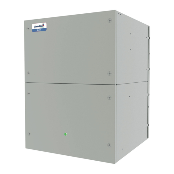
Page 6: Unit Overview
Ecotel™ FreeCool Telecoms Unit Overview Front View Removable Front Panel with Door Seal Mounting Bracket Tamper Proof Fixings Removable Centrifugal EC Fan Rear View G4 Air Filter Control Panel Ecotel™ FreeCool 5-15kW Technical Manual 9368648 v1.6.0 12_2016... -
Page 7: Case Sizes
Case Sizes The Ecotel range shall have a total of 2 case sizes. 5kW & 10kW utilise the same case dimensions, the 15kW has a larger case size to house a larger fan. Case Size ET05D ET10D ET15D Width (mm) -
Page 8: Airflow Components
Ecotel™ FreeCool Telecoms Airflow Components EC centrifugal fan Spring Return Air Damper Actuator Fire Rated Damper System Configuration ET05D ET10D ET15D Features ● ● ● Backward Curved EC Fan ○ ○ ○ -48VDC Centrifugal Fan ● ● ● G4 Filtration ○... - Page 9 Telecoms Ecotel™ FreeCool Electronically Commutated (EC) Fan Motor EC motors incorporate integrated electronics to convert AC power to DC for efficient and accurate speed control and are adjustable via the microprocessor display keypad. The fans offer maximum air flow performance while keeping sound levels to a minimum. It gives the flexibility of connecting to AC mains with the efficiency and simple speed control of a DC motor.
-
Page 10: Electrical Components
Ecotel™ FreeCool Telecoms Electrical Components Transformer pCO5 built in controller Thermostat Air Flow Switch Advanced Control Panel System Configuration ET05D ET10D ET15D Features ● ● ● Mains Isolator ○ ○ ○ Energy Manager* ● ● ● 230V/1PH + N/50Hz ○... - Page 11 Telecoms Ecotel™ FreeCool Isolator Local Isolator (Typical Placement) Mains Isolator To comply with BS EN 6024-1:2006 Safety of Machinery – Electrical Equipment Machines, each unit should have an accompanying isolator (switch disconnecting device). The supply disconnecting device shall isolate the electrical equipment of the telecoms unit from the electrical supply when required.
-
Page 12: Controls
Ecotel™ FreeCool Telecoms Controls pCO5 Compact Controller IR33 Controller System Configuration ET05D ET10D ET15D Features ● ● ● IR33 inbuilt microcontroller ● ● ● pCO5 compact microcontroller* ○ ○ ○ Remote Display* ○ ○ ○ LED Alarm Indicator* ○ ○... - Page 13 • Programmable modbus interface The control system integrity shall be maintained by restricting access with a password PIN IMPORTANT number. To change the PIN , please contact Airedale at time of order with the preferred 4 digit number. Display/Keypad The display keypad shall feature a simple array of keys to navigate through the in built menus.
- Page 14 Ecotel™ FreeCool Telecoms Display Icons - PC05 To ensure the software is easy to read at a glance and to make translations easier, the Ecotel user interface is largely graphical, containing a large number of icons to represent different modes, actions or components. The following table is a glossary of icons to use as a reference: Icon Name/Description...
- Page 15 A wide range of protocols shall be accommodated through the use of interface devices. Available as a standard option are: ModBus/Jbus, and Carel. For interfaces such as SNMP, LonWorks, Metasys and BACnet, please contact Airedale. Also available shall be Airedale’s own supervisory plug-in BMS card pCOWEB, based on Ethernet TCP/IP secure technology with SNMP features.
-
Page 16: External
Ecotel™ FreeCool Telecoms External M5 x 12mm (8) Tamper Proof Fixings System Configuration ET05D ET10D ET15D Features ● ● ● Mounting Bracket ● ● ● M5/M8 Tamper Proof Fixings ○ ○ ○ Mounting Template ○ ○ ○ Anti Vandal Cage ●... -
Page 17: Product Operation
Telecoms Ecotel™ FreeCool Product Operation Free Cooling Mode The temperature sensor for the unit shall measure the exhaust air temperature of the cabin at the opposite cabin wall to the unit. The unit shall vary the fan speed to increase/decrease the air volume to maintain a constant room temperature set point. -
Page 18: Installation
Remove packing and check that the unit is exactly as ordered. Any discrepancy to order, or transit damage, should be reported to Airedale immediately • Airedale recommends that whenever possible, the packaging is left covering the unit, to protect it from damage and general site debris •... -
Page 19: Positioning
Telecoms Ecotel™ FreeCool Installation Positioning WEATHER LOUVRE EXHAUST DAMPER Supply air Exhaust air The unit must be positioned at least 600mm from the ground to supply the cabin space with cool air at a lower point and allow the warm air rise to up to a higher exhaust on the opposite side of the cabin. This should allow even air distribution and maximise performance of the unit’s application. -
Page 20: Dimensions
Ecotel™ FreeCool Telecoms Installation Dimensions ET05-10D DISCHARGE AIR CUSTOMER INCOMING CABLES CABIN WALL CUSTOMER INCOMING CABLES FRESH AIR INTAKE Min. 600mm from ground Ecotel™ FreeCool 5-15kW Technical Manual 9368648 v1.6.0 12_2016... - Page 21 Telecoms Ecotel™ FreeCool Installation Dimensions ET05-10D - Wall Mount Bracket A - ø 9.7mm Fixing Holes DISCHARGE AIR WALL APERTURE Bracket Mass = 3.2kg Ecotel™ FreeCool 5-15kW Technical Manual 9368648 v1.6.0 12_2016...
- Page 22 Ecotel™ FreeCool Telecoms Installation Dimensions ET15D DISCHARGE AIR CUSTOMER INCOMING CABLES CABIN WALL CUSTOMER INCOMING CABLES Min. 600mm from ground FRESH AIR INTAKE Ecotel™ FreeCool 5-15kW Technical Manual 9368648 v1.6.0 12_2016...
- Page 23 Telecoms Ecotel™ FreeCool Installation Dimensions ET15D - Wall Mount Bracket A - ø 9.7mm Fixing Holes Bracket Mass = 4.4kg Ecotel™ FreeCool 5-15kW Technical Manual 9368648 v1.6.0 12_2016...
-
Page 24: Incoming Services
Ecotel™ FreeCool Telecoms Installation Incoming Services ET05-10D 20mm GALVANISED COUPLERS (CUSTOMER CABLES) A minimum of 2mm clearance is required for all incoming services. REAR SIDE ET15D 20mm GALVANISED COUPLERS (CUSTOMER CABLES) REAR SIDE Ecotel™ FreeCool 5-15kW Technical Manual 9368648 v1.6.0 12_2016... -
Page 25: Exhaust Installation
Telecoms Ecotel™ FreeCool Installation Exhaust Installation ET05-15D CEILING LEVEL MIN 200MM FROM CEILING TO CUTOUT Flanges shall be 25mm wide. 600MM X 600MM WALL CUTOUT WEATHER LOUVRE EXHAUST DAMPER Ecotel™ FreeCool 5-15kW Technical Manual 9368648 v1.6.0 12_2016... -
Page 26: Technical Data
Ecotel™ FreeCool Telecoms Technical Data ET05D-FS0-7 - ET05D-FS0-8 - ET05D-FS0-9 ET05D Mechanical Data ET05D-FS0-7 ET05D-FS0-8 ET05D-FS0-9 Capacity - Nom Cooling Total Sensible 29.6 29.6 29.6 Variable Variable Variable Capacity Steps Capacity - Free Cooling (2) m³/s Max Airflow Dimensions 560 x 740 x 560... - Page 27 Telecoms Ecotel™ FreeCool Technical Data ET05D-FS1-7 - ET05D-FS1-8 - ET05D-FS1-9 ET05D Mechanical Data ET05D-FS1-7 ET05D-FS1-8 ET05D-FS1-9 Capacity - Nom Cooling Total Sensible 30.6 30.6 30.6 Variable Variable Variable Capacity Steps Capacity - Free Cooling (2) m³/s Max. Airflow Dimensions 560 x 740 x 560...
- Page 28 Ecotel™ FreeCool Telecoms Technical Data ET05D-FA0-7 - ET05D-FA0-8 - ET05D-FA0-9 ET05D Mechanical Data ET05D-FA0-7 ET05D-FA0-8 ET05D-FA0-9 Capacity - Nom Cooling Total Sensible 29.6 29.6 29.6 Variable Variable Variable Capacity Steps Capacity - Free Cooling (2) m³/s Max Airflow Dimensions 560 x 740 x 560...
- Page 29 Telecoms Ecotel™ FreeCool Technical Data ET05D-FA1-7 - ET05D-FA1-8 - ET05D-FA1-9 ET05D Mechanical Data ET05D-FA1-7 ET05D-FA1-8 ET05D-FA1-9 Capacity - Nom Cooling Total Sensible 30.6 30.6 30.6 Variable Variable Variable Capacity Steps Capacity - Free Cooling (2) m³/s Max. Airflow Dimensions 560 x 740 x 560...
-
Page 30: Et10D
Ecotel™ FreeCool Telecoms Technical Data ET10D-FS0-7 - ET10D-FS0-8 - ET10D-FS0-9 ET10D Mechanical Data ET10D-FS0-7 ET10D-FS0-8 ET10D-FS0-9 Capacity - Nom Cooling Total Sensible 17.4 17.4 17.4 Variable Variable Variable Capacity Steps Capacity - Free Cooling (2) m³/s 1.03 1.03 1.03 Max. Airflow Dimensions 560 x 740 x 560 560 x 740 x 560... - Page 31 BS EN 779-M5 Filtration Quantity 506 x 540 x 45 506 x 540 x 45 506 x 540 x 45 Size W x H x D Electrical Data ET05D-FS1-7 ET05D-FS1-8 ET05D-FS1-9 Electrical Supply Data Mains Supply -48VDC -48VDC -48VDC Controls Circuit...
- Page 32 Ecotel™ FreeCool Telecoms Technical Data ET10D-FA0-7 - ET10D-FA0-8 - ET10D-FA0-9 ET10D Mechanical Data ET10D-FA0-7 ET10D-FA0-8 ET10D-FA0-9 Capacity - Nom Cooling Total Sensible 17.4 17.4 17.4 Variable Variable Variable Capacity Steps Capacity - Free Cooling (2) m³/s 1.03 1.03 1.03 Max. Airflow Dimensions 560 x 740 x 560 560 x 740 x 560...
- Page 33 Telecoms Ecotel™ FreeCool Technical Data ET10D-FA1-7 - ET10D-FA1-8 - ET10D-FA1-9 ET10D Mechanical Data ET10D-FA1-7 ET10D-FA1-8 ET10D-FA1-9 Capacity - Nom Cooling Total Sensible 22.7 22.7 22.7 Variable Variable Variable Capacity Steps Capacity - Free Cooling (2) m³/s Max. Airflow Dimensions 560 x 740 x 560 560 x 740 x 560 560 x 740 x 560 W x H x D...
-
Page 34: Et15D
Ecotel™ FreeCool Telecoms Technical Data ET15D-FS0-7 - ET15D-FS0-8 - ET15D-FS0-9 ET15D Mechanical Data ET15D-FS0-7 ET15D-FS0-8 ET15D-FS0-9 Capacity - Nom Cooling Total Sensible 16.2 16.2 16.2 Variable Variable Variable Capacity Steps Capacity - Free Cooling (2) m³/s Max Airflow Dimensions 730 x 850 x 730 730 x 850 x 730 730 x 850 x 730 W x H x D... - Page 35 Telecoms Ecotel™ FreeCool Technical Data ET15D-FS1-7 - ET15D-FS1-8 - ET15D-FS1-9 ET15D Mechanical Data ET15D-FS1-7 ET15D-FS1-8 ET15D-FS1-9 Capacity - Nom Cooling Total Sensible 23.9 23.9 23.9 Variable Variable Variable Capacity Steps Capacity - Free Cooling (2) m³/s Max. Airflow Dimensions 730 x 850 x 730 730 x 850 x 730 730 x 850 x 730 W x H x D...
- Page 36 Ecotel™ FreeCool Telecoms Technical Data ET15D-FA0-7 - ET15D-FA0-8 - ET15D-FA0-9 ET15D Mechanical Data ET15D-FA0-7 ET15D-FA0-8 ET15D-FA0-9 Capacity - Nom Cooling Total Sensible 16.2 16.2 16.2 Variable Variable Variable Capacity Steps Capacity - Free Cooling (2) m³/s Max. Airflow Dimensions 730 x 850 x 730 730 x 850 x 730 730 x 850 x 730 W x H x D...
- Page 37 Telecoms Ecotel™ FreeCool Technical Data ET15D-FA1-7 - ET15D-FA1-8 - ET15D-FA1-9 ET15D Mechanical Data ET15D-FA1-7 ET15D-FA1-8 ET15D-FA1-9 Capacity - Nom Cooling Total Sensible 23.9 23.9 23.9 Variable Variable Variable Capacity Steps Capacity - Free Cooling (2) m³/s Max. Airflow Dimensions 730 x 850 x 730 730 x 850 x 730 730 x 850 x 730 W x H x D...
-
Page 38: Performance Data
10.0 15.0 20.0 25.0 30.0 35.0 Ambient Temperature (°C) R.A.T @ 25°C R.A.T @ 30°C R.A.T @ 35°C ET05D 25.0 ET05D-F*0 -* 20.0 15.0 10.0 R.A.T @ 25°C R.A.T @ 30°C R.A.T @ 35°C 10.0 15.0 20.0 25.0 30.0 35.0 Ambient Temperature (°C) - Page 39 Telecoms Ecotel™ FreeCool Performance Data ET10D 45.0 ET10D-F*0 -* 40.0 35.0 30.0 25.0 20.0 15.0 10.0 R.A.T @ 30°C R.A.T @ 25°C R.A.T @ 35 ° C 10.0 15.0 20.0 25.0 30.0 35.0 Ambient Temperature (°C) R.A.T @ 25°C R.A.T @ 30°C R.A.T @ 35°C ET15D ET15D-F*0 -*...
-
Page 40: Sound Data
AC Power Supply Frequency (Hz) dB Overall Sound Measurement dB(A) 1000 2000 4000 8000 Power Sound pressure @1m ET05D-FS0 Sound pressure @3m Sound pressure @10m Power Sound pressure @1m ET10D-FS0 Sound pressure @3m Sound pressure @10m Power Sound pressure @1m ET15D-FS0... - Page 41 DC Power Supply Frequency (Hz) dB Overall Sound Measurement dB(A) 1000 2000 4000 8000 Power Sound pressure @1m ET05D-FS1 Sound pressure @3m Sound pressure @10m Power Sound pressure @1m ET10D-FS1 Sound pressure @3m Sound pressure @10m Power Sound pressure @1m ET15D-FS1...
-
Page 42: Installation Wiring
Ecotel™ FreeCool Telecoms Installation Wiring Power Connections Mains Incoming Supply Indoor Unit (230V / 1PH / + N / 50Hz or 220V / 1PH / +N / 60Hz) Mains Incoming Supply Indoor Unit (220V / 2PH / 60Hz) ... - Page 43 Telecoms Ecotel™ FreeCool Intstallation Wiring Advance Control Connections 500 (800) Cabin Temperature Sensor 1 500 (800) Cabin Temperature Sensor 2 500 (800) Option Cabin Temperature Sensor 3 500 (800) Cabin Temperature Sensor 4 ...
-
Page 44: Plan Termination
Ecotel™ FreeCool Telecoms pLAN Termination pLAN Termination The plugged termination ensures that the connections are made simultaneously. Failure to attach the cables this way may cause damage to the controller. Customer Side RxTx - RxTx + RxTx - RxTx + Panel Side Ecotel™... -
Page 45: Maintenance
Telecoms Ecotel™ FreeCool Maintenance Owner’s Responsibility To ensure that the unit can be maintained correctly ensure the following requirements are met. Maintain a safe working environment around the unit, free from obstructions and debris. The unit shall follow the following maintenance regime as a minimum: The equipment contains live electrical and moving parts, ISOLATE prior to maintenance or repair IMPORTANT work. -
Page 46: General Inspections
Ecotel™ FreeCool Telecoms Maintenance General Inspections Frequency Task 3 Mths Mths Mths Check for visible mechanical damage to unit. ● General Inspections Visually inspect the unit for general wear and tear, treat metalwork. ● Rust should be inhibited, primed and touched up with matching paint. -
Page 47: Filter Removal
Telecoms Ecotel™ FreeCool Maintenance General Inspections Procedures Filter Removal The procedure outlined below should be followed to remove the unit filter: • Check all services are isolated and the unit is safe to work on. • Remove the tamper proof fixings from the sides of the front panel and remove. •... -
Page 48: Electrical Inspections
Ecotel™ FreeCool Telecoms Maintenance Electrical Inspections Frequency Task 3 Mths Mths Mths Electrical Check main power supply voltages ● Inspections Check electrical terminals are tight. ● Check for signs of hot spots/discolouration on power cables. ● Check amperages are as per design. ●... -
Page 49: Controls
Telecoms Ecotel™ FreeCool Maintenance Controls Frequency Task Controls 3 Mths Mths Mths Change controller battery.* ● Service Tools/Test Equipment Safety Equipment • Small Terminal Screwdriver • Electrostatic Wristband *The controller will keep the strategy for a short period of time with no battery. Ecotel™... -
Page 50: Troubleshooting
Ecotel™ FreeCool Telecoms Troubleshooting FAULT POSSIBLE CAUSE REMEDY/ACTION Unit not operating - Power Off. Main/local isolator off Check all isolators from mains to unit. Check all mains fuses. Replace after Mains Fuse(s) failed. correcting fault. Check for loose wire. Unit not operating - Power Unit not switched on. -
Page 51: Alarms
Telecoms Ecotel™ FreeCool Alarms PC05 Compact Only Alarm Menu Display Alarm number Alarm name Alarm Status Time Date Alarm Log The alarm page offers a log of the last 150 alarm messages in a scrolling log, pressing the alarm button will enter the alarm page. - Page 52 Ecotel™ FreeCool Telecoms Alarms The following lists display all alarms available in the Ecotel FreeCool. Some of these alarms may not be available depending on unit type and selected options. Code Name Description Action Reset Importance Power Restart Mains power restarted For information Auto Non-Critical...
-
Page 53: After Sales
All Airedale products or parts (non consumable) supplied for installation within the UK mainland and commissioned by an Airedale engineer, carry a full Parts & Labour warranty for a period of 12 months from the date of commissioning or 18 months from the date of despatch, whichever is the sooner. - Page 54 Head Offi ce Airedale International Air Conditioning Ltd Leeds Road Rawdon Leeds LS19 6JY Tel: +44 (0) 113 2391000 Fax:+44 (0) 113 2507219 E-mail enquiries@airedale.com Web www.airedale.com TM_EcotelFreeCooling_9368648_5-15kW_V1.6.0_12_2016...
Need help?
Do you have a question about the ET05D and is the answer not in the manual?
Questions and answers