Table of Contents
Advertisement
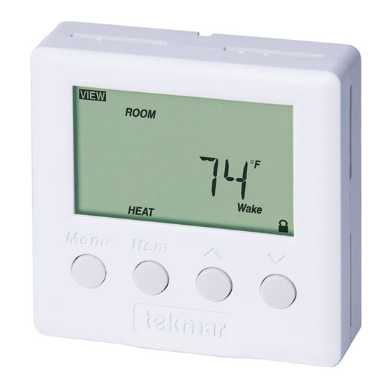
Programmable Thermostat 512
Table of Contents
Display / Keypad Operation ............ pg 1
Display Symbols ............................. pg 2
General ........................................ pg 2-3
Sequence of Operation................pg 4-6
Type 512 (Two Stage Heating) ... pg 4
Type 512 (Heat / Cool) ............pg 5-6
Menus ........................................ pg 6-10
Display / Keypad Operation
The thermostat's display has four distinct fields. These fields are the Menu field, the Item
field, the Number field and the Status field. The four buttons on the face of the thermostat are
used to navigate through the menus and items to view and / or adjust the desired settings.
Displays the
current
menu
Displays the current
status of the
thermostat's inputs,
outputs and operation
- Data Brochure
1 of 20
View Menu ................................ pg 6
Adjust Menu ........................pg 7-10
Error Messages ......................pg 11
Installation .................................pg 12-13
Wiring the 512 ...........................pg 14-17
Warranty ....................................... pg 20
Displays an abbreviated
name of the selected item
Selects Menus, Items
and adjusts settings
© 2009
D 512
09/09
Displays the current value
of the selected item
D 512 - 09/09
Advertisement
Table of Contents

Related Manuals for Tekmar D 512


Summary of Contents for Tekmar D 512
-
Page 1: Table Of Contents
Displays the current value of the selected item Displays the current status of the thermostat's inputs, outputs and operation Selects Menus, Items and adjusts settings 1 of 20 © 2009 D 512 - 09/09... -
Page 2: Display Symbols
30 minutes prior to the beginning of a period that requires cooling. NOTE: The Early Start feature occurs when the schedule changes from a low temperature to a higher temperature. © 2009 D 512 - 09/09 2 of 20... - Page 3 ACCESS LEVELS The tekmar Programmable Thermostat has two access levels. These access levels restrict the number of items available in the menus of the thermostat.
-
Page 4: Sequence Of Operation
NOTE: If an air or slab sensor is active in the Off mode, a freeze protection is enabled that allows the relays to be operated to keep the zone above 35°F (2°C). © 2009 D 512 - 09/09 4 of 20... -
Page 5: Type 512 (Heat / Cool)
NOTE: If an air or slab sensor is active in the Off mode, a freeze protection is enabled that allows the Heat 1 relay to be operated to keep the zone above 35°F (2°C) 5 of 20 © 2009 D 512 - 09/09... -
Page 6: Menus
(Must have an active slab sensor. If two slab sensors are present, this is the average temperature.) The MIN segment is displayed when running on Min. REMOTE The current temperature at the remote sensor. (Sens 1 must be set to Rem.) © 2009 D 512 - 09/09 6 of 20... -
Page 7: Adjust Menu
35 to 100°F (1.5 to 38.0°C) ROOM HEAT Sleep Desired temperature for heating during Sleep. (Must have an active air sensor and be set to either Heat or Auto.) 35 to 100°F (1.5 to 38.0°C) 7 of 20 © 2009 D 512 - 09/09... - Page 8 (Must have an active slab sensor.) OFF, 34 to 122°F (OFF, 1.0 to 50.0°C) SLAB MINIMUM Sleep Minimum slab temperature during Sleep. (Must have an active slab sensor.) OFF, 34 to 122°F (OFF, 1.0 to 50.0°C) © 2009 D 512 - 09/09 8 of 20...
- Page 9 COOLING MINIMUM ON Sets the minimum on time of the cooling contact. This is to prevent short cycling. This item is only available in the Installer access level. 0:30 to 5:00 min. 9 of 20 © 2009 D 512 - 09/09...
-
Page 10: Menus
Installer access level. OFF, ON LITE Sets the operation of the backlighting of the LCD. ON, Tmpy ON, OFF UNITS The units of temperature used to display the items. °F, °C © 2009 D 512 - 09/09 10 of 20... -
Page 11: Error Messages
The auxiliary sensor connected to the Sens 2 terminal is open circuit. Locate and repair the problem as described in the appropriate sensor brochure. After the fault is corrected, press any button to clear the error message. 11 of 20 © 2009 D 512 - 09/09... -
Page 12: Installation
Check the contents of this package. If any of the contents are missing or damaged, please contact your wholesaler or tekmar sales representative for assistance. Type 512 Includes: • • One Programmable Thermostat 512 • • Data Brochure D 512 • User Brochure U 512... - Page 13 Pivot the front cover around the bottom hinges and push the top against the mounting base until it snaps firmly in place. Pivot front cover around bottom hinges Align hinges on bottom of front cover 13 of 20 © 2009 D 512 - 09/09...
-
Page 14: Wiring The 512
WIRING 24 V (AC) POWER AND AUXILIARY SENSORS 120 V (ac) 24 V (ac) Sensor Wires Auxiliary Sensor (Optional) WIRING THE 512 One Stage with Zone Valve and Cooling Cooling Zone Valve 24 V (ac) Class 2 Transformer © 2009 D 512 - 09/09 14 of 20... - Page 15 Unpowered Relay Cooling Zone Pump 24 V (ac) Class 2 Transformer Two Stage Heat with Zone Valves Stage 1 Zone Valve Stage 2 Zone Valve 24 V (ac) Class 2 Transformer 15 of 20 © 2009 D 512 - 09/09...
- Page 16 Valve 24 V (ac) Class 2 Transformer Two Stage with Zone Pump and Zone Valve Unpowered Relay Stage 2 Zone Valve Stage 1 Zone Pump 24 V (ac) Class 2 Transformer © 2009 D 512 - 09/09 16 of 20...
- Page 17 24 V (ac) Class 2 Transformer Two Stage with Zone Pumps Typical Powered Typical Powered Relay Relay Stage 1 Stage 2 Zone Zone Pump Pump 24 V (ac) Class 2 Transformer 17 of 20 © 2009 D 512 - 09/09...
- Page 18 Notes © 2009 D 512 - 09/09 18 of 20...
- Page 19 Notes 19 of 20 © 2009 D 512 - 09/09...
-
Page 20: Warranty
Prod- uct was not installed in compliance with tekmar’s instructions and / or the local codes and ordinances; or if due to defective installation of the Product; or if the Product was not used in compliance with tekmar’s instructions.
Need help?
Do you have a question about the D 512 and is the answer not in the manual?
Questions and answers