Advertisement
- Data Brochure
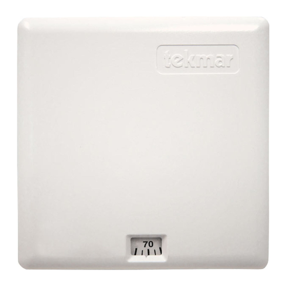
Room Temperature Unit (RTU) 054
The tekmar Room Temperature Unit (RTU) 054 consists of a temperature sensor and
an adjustable dial which is used to set the desired indoor temperature. The RTU 054 dial
has a temperature range from 40 to 100°F (4 to 38°C). In cases where a restricted
temperature range is required, the dial rotation can be limited using limit pins supplied
with the RTU. A 10K temperature sensor (e.g. 071, 072 etc.) can be mounted remote
from the RTU. This RTU does not work with older tekmar controls. If the RTU is to be
70
mounted on a 2" x 4" electrical box, an Adaptor Plate 007 is available for use.
Installation
STEP ONE
• Place a screwdriver or similar object into the small slot located in the top of the RTU.
• Push the screwdriver against the plastic flap and pull the top of the front cover so that it pivots
around the bottom edge of the RTU.
STEP TWO
• The RTU should be installed on an interior wall of the desired zone to be controlled. Do not mount the RTU in a location that may be
affected by localized heat sources or cold drafts. It may be necessary to install a draft barrier behind the enclosure in order to prevent
air from blowing through the wiring hole and affecting the RTU reading.
• Mount the RTU directly to the wall using two #6-1" screws. The screws are inserted through
the mounting holes and must be securely fastened to the wall. If possible one of the screws
should enter a wall stud.
STEP THREE
Run 18 AWG or similar wire between the RTU and the Com Sen-RTU terminals on the control.
Insert the wires through the hole provided in the back of the RTU enclosure and connect them
to the RTU terminal block. Do not run the wires parallel to telephone or power lines. If the RTU
wires are located in an area with strong sources of electromagnetic noise, shielded cable or
twisted pair should be used or the wires can be run in a grounded metal conduit.
If installing a remote temperature sensor, connect its two wires also to the RTU terminal block
and cut the jumper in the RTU enclosure. For best accuracy, the RTU and the remote sensor
should be approximately at the same temperature.
STEP FOUR
A good quality test meter capable of measuring up to 5000 kΩ ( 1 kΩ = 1000 Ω) is required to
measure the sensor resistance. In addition to this, the actual temperature must be measured
with either a good quality digital thermometer or if a thermometer is not available, a second
sensor can be placed alongside the one to be tested and the readings compared.
First measure the room temperature using the thermometer. The RTU must be disconnected from the control before it is tested. Turn
the RTU dial to 70°F (21°C). Measure the resistance of the RTU by touching the test leads on the wires running to the RTU. Reverse
the leads and measure the RTU resistance again. The lower "Ohm" reading is the combined resistance of the dial and the sensor, and
the higher "Ohm" reading is the resistance of the sensor alone.
Using the chart below, estimate the room temperature based on the sensor only (highest) resistance measurement. Compare the sensor
temperature measurement with the thermometer reading. If the sensor temperature is significantly above the thermometer reading, the
wiring may be shorted, moisture may be in the sensor or the sensor may be defective. If the sensor temperature is significantly below
the thermometer reading, there may be a broken wire, a loose connection or a defective sensor.
°F
48
50
Temperature
°C
9
10
Resistance (kΩ)
20.8
19.7
If a defective sensor is suspected, first check the wiring from the RTU to the control and then
measure the sensor resistance directly at the RTU terminals using the above procedure.
STEP FIVE
• Align the hinges on the bottom of the front cover with the bottom of the RTU mounting base.
• Pivot the front cover around the bottom hinges and push the top against the mounting base
until it snaps firmly into place.
REMOVING THE FRONT COVER
MOUNTING THE RTU
WIRING THE RTU
TESTING THE RTU
52
54
56
58
11
12
13
14
18.7 17.7
16.8
15.9
INSTALLING THE FRONT COVER
60
62
64
66
68
16
17
18
19
20
15.0
14.3
13.5
12.8
12.2
1 of 2
Top view of RTU
To control
terminals
(Com Sen — RTU)
Wall Stud
Mounting the RTU
70
72
74
76
78
21
22
23
24
26
11.5
10.9
10.4
9.8
9.3
Installing the
front cover
Copyright © D 054 - 06/00
D 054
06/00
Small slot for
screwdriver
RTU terminals
Jumper
#6-1" screws
80
82
84
27
28
29
8.8
8.4
7.9
Advertisement
Table of Contents

Related Manuals for Tekmar D 054


Summary of Contents for Tekmar D 054
- Page 1 RTU. A 10K temperature sensor (e.g. 071, 072 etc.) can be mounted remote from the RTU. This RTU does not work with older tekmar controls. If the RTU is to be mounted on a 2" x 4" electrical box, an Adaptor Plate 007 is available for use.
- Page 2 The liability of tekmar under this warranty shall be limited to, at tekmar's sole discre- Governing Law (being the law of British Columbia) allows parties to contractu- tion: the cost of parts and labor provided by tekmar to repair defects in materials and/ ally exclude, including, without limitation, warranties of merchantability, or workmanship of the defective product;...
Need help?
Do you have a question about the D 054 and is the answer not in the manual?
Questions and answers