Subscribe to Our Youtube Channel
Summary of Contents for IN-COMMAND Lite
- Page 1 ™ RV CONTROL AND MONITORING SYSTEM Installation and Operation Manual Patent # 9,679,644...
-
Page 3: Important Safety Information
Important Safety Information Read the iN-Command Manual, and these warnings and instructions carefully before using this product. Failure to follow the use instructions in this owner’s manual, or improper use of the Mobile Application, Display Commander and/or Body Control Module, could result in personal injury, including death. -
Page 4: Table Of Contents
• TABLE OF CONTENTS TABLE OF CONTENTS ............3 INTRODUCTION ..............4 Thank You! ................4 Features .................4 Precautions ................4 Packing List ................4 INSTALLATION ................5 Tools and Supplies ..............5 Disconnecting the Battery ............5 Selecting the Mounting Location ..........5 Mounting the Display Commander (DC) ........5 Mounting the Switch Plate (SP) ..........5 WIRING ...................6 APP SETUP MENU LIST ............7... -
Page 5: Introduction
If you take a few minutes to look through it, you’ll learn how to use all the features of your new iN-Command Lite for maximum enjoyment. • Features Features of iN-Command Lite system: •... -
Page 6: Installation
• Mounting the Display Commander (DC) • INSTALLATION • Cut/Drill hole, allowing space below for future programming and It’s a good idea to read all of the instructions before beginning the behind for ventilation installation. We recommend having your iN-Command system •... -
Page 7: Wiring
• WIRING The wiring diagram depicts all the wiring connections required for proper operation of the unit. The TX (transmit) and RX (receive) connections at each device are crossed (crossover cable). BODY CONTROL MODULE (BCM) CONNECTIONS PIN NO. WIRE GAUGE DESCRIPTION PIN NO. -
Page 8: App Setup Menu List
• APP SETUP MENU LIST ITEM SELECTION One light group and seven motor functions can be added or removed Light Group 1 No, Yes via a downloadable App from Google and Apple stores. Motor 1 No, Yes Motor functions may include slides, awnings, jacks, or any motor that Motor 2 No, Yes may be controlled with a momentary switch. -
Page 9: Travel Lockout (Safety)
• TRAVEL LOCKOUT (SAFETY) iN-Command is equipped with a Travel Lockout feature to ensure certain system functions are unavailable during transit. When the Brake on the vehicle is activated, iN-Command will lock out (disable) all motorized functions. If the Switch Plate (SP) is installed, the Travel Lock LED will be solid red. -
Page 10: Trouble Shooting
• TROUBLE SHOOTING Symptom Solution Verify the BCM is powered on. Check main fuse in Distribution Panel. Display Commander (DC) will not turn ON Check 12V+ on wire to DC (RED wire). Check Ground wire to DC. Check if the Red power LED is off, Check the fuse in the Distribution Panel. -
Page 11: Switch Plate Buttons
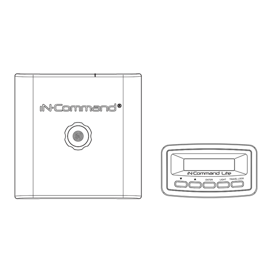
• SWITCH PLATE BUTTONS The SP (Switch Plate) has 2 buttons on the front of it. From left to right, they are: • Travel Lock • Bluetooth Pairing The Travel Lock button turns off the Travel Lock function when the light is flashing red. -
Page 12: Specifications
• SPECIFICATIONS • Federal Communications Commission (FCC) Statement NCS50DC (Display Commander) 15.21 You are cautioned that changes or modifications not expressly approved Operating Voltage ....... . 12VDC by the part responsible for compliance could void the user’s authority to Maximum Current Draw . -
Page 13: Mobile Devices
• MOBILE DEVICES: iN-Command Lite is able to pair to Android and iOS devices via the mobile App. Visit the Google Play and Apple App stores on your mobile device to download and use the iN-Command Lite App. Only One mobile device is able to be paired with... -
Page 14: Pairing Mobile Device To Dc/Sp
• Pairing Mobile Device to DC/SP 1. Open NCS Lite application on device. 3. Press “Select” button to connect the SP or DC. 2. Press the gear cog to enter the settings page. 4. Press device name to connect. - Page 15 5. Remote device will show pairing message. 6. If connection is successfully established, setting page The SP will flash a blue light. will show connected device name and versions. The DC will flash " Accept new device on display" Press "ENTER" or "BLUETOOTH PAIRING" button to Pair. To connect NCS50DC/SP with another device.
-
Page 16: Ncs50Dc/Sp Firmware Update
• NCS50DC/SP FIRMWARE UPDATE* 1. Press “Update” button to update NCS50DC/NCS50SP. 2.2 For Android: Wait for Wi-Fi connection, then press start button. 2.1 For iOS: In Wi-Fi Settings, connect to Wi-Fi network shown on app. 3. For iOS : Once connected to network, go back to app, App will Password is “1234567890”. -
Page 17: Edit And Reset Floor Plan
• EDIT AND RESET FLOOR PLAN 4. App will display "Update complete" once firmware is update Press Dismiss button. DC/SP will reboot with new firmware. 1. From the Apps Home Page, press the gear cog at the lower right corner to enter the Settings Page. 5. - Page 18 3. To Edit the floor plan, press the Edit button. 5. To add or remove functions, press the box next to the function. 4. In the Edit Menu, you can add or remove functions, 6. To reposition a function, press and hold the "≡" icon next to the reposition function and edit the text for the function.
- Page 19 7. To edit the text, press on the function text. A device rename window will open. Press "OK" after completing text editing. (The text box is Limited to 12 characters) 8. Once changes have been made, press the Save button at the top of the page.
- Page 20 www.jensenrvdirect.com ©2015 ASA Electronics LLC MA-1612004A-1R...


Need help?
Do you have a question about the Lite and is the answer not in the manual?
Questions and answers