Advertisement
Table of Contents
- 1 Table of Contents
- 2 Safety Instructions
- 3 Assembly (for Use with Workhorse Trap and Included Tripod Stand)
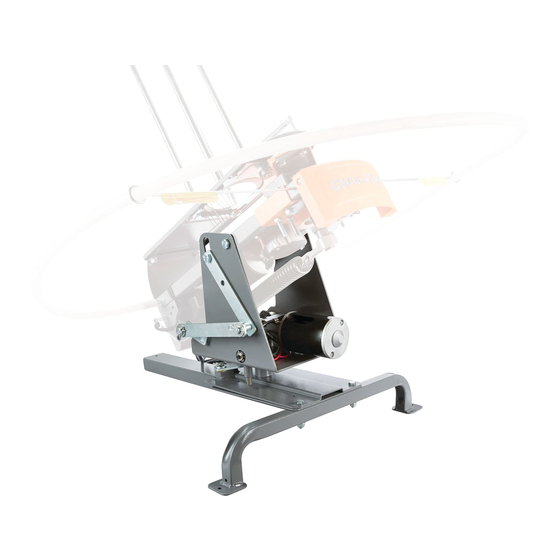
- 4 Assembly of Workhorse Trap Onto Wobble Bird Base with Tripod Stand
- 5 Assembly of Wobble Bird Base with Trap Taxi (Not Included)
- 6 Assembly of Wheelybird Trap Onto Wobble Bird Base with Trap Taxi (Not Included)
- 7 Wobble Bird Operation (Standard Dual Axis Motion)
- 8 Wobble Bird Operation (Alternate Single Axis Motion: Left/Right Only)
- 9 Wobble Bird Operation (Alternate Single Axis Motion: Up/Down Only)
- 10 Troubleshooting
- Download this manual
Advertisement
Table of Contents


Need help?
Do you have a question about the WOBBLE BIRD and is the answer not in the manual?
Questions and answers