Table of Contents
Advertisement
Quick Links
Advertisement
Table of Contents

Subscribe to Our Youtube Channel
Related Manuals for Woodward 505XT


Summary of Contents for Woodward 505XT
- Page 1 Product Manual 35018V1 (Revision B, 2/2017) Original Instructions 505XT Digital Control for Steam Turbines (Single valve, Extraction and/or Admission) 8200-1310, 8200-1311, 8200-1312 Manual 35018 consists of 2 volumes (35018V1 & 35018V2) Installation and Operation Manual Volume 1...
- Page 2 Revisions— A bold, black line alongside the text identifies changes in this publication since the last revision. Woodward reserves the right to update any portion of this publication at any time. Information provided by Woodward is believed to be correct and reliable. However, no responsibility is assumed by Woodward unless otherwise expressly undertaken.
-
Page 3: Table Of Contents
Manual 35018V1 505XT Digital Control System for Steam Turbines Contents ....................... 6 ARNINGS AND OTICES ..................8 LECTROSTATIC ISCHARGE WARENESS ......................9 EGULATORY OMPLIANCE 1. G .................... 14 HAPTER ENERAL NFORMATION Introduction ..............................14 Controller Overview ............................. 14 ... - Page 4 Manual 35018V1 505XT Digital Control System for Steam Turbines Extraction/Admission Control ........................89 Steam Performance Map Menu ........................95 Inlet Steam Pressure Control ........................108 Exhaust Steam Pressure Control ......................109 HP Valve Limiter ............................110 ...
- Page 5 Manual 35018V1 505XT Digital Control System for Steam Turbines Returning Equipment for Repair ....................... 223 Replacement Parts ............................ 224 Engineering Services ..........................224 Contacting Woodward’s Support Organization ..................224 Technical Assistance ..........................225 A. 505XT C ............
- Page 6 Manual 35018V1 505XT Digital Control System for Steam Turbines Figure 3-11. Speed PID Control Modes ...................... 66 Figure 3-12. Frequency and Unit Load Relationship .................. 67 Figure 3-13. Speed Relationships ....................... 69 Figure 3-14. Load Sharing Logic ......................... 75 ...
- Page 7 Manual 35018V1 505XT Digital Control System for Steam Turbines Table 1-1. Selectable functions for 4-20mA Analog Inputs ................. 19 Table 1-2. Selectable functions for Discrete Inputs ..................20 Table 1-3. Selectable functions for 4-20mA Analog Outputs ..............21 ...
-
Page 8: Warnings And Notices
Manual 35018V1 505XT Digital Control System for Steam Turbines Warnings and Notices Important Definitions This is the safety alert symbol used to alert you to potential personal injury hazards. Obey all safety messages that follow this symbol to avoid possible injury or death. - Page 9 Manual 35018V1 505XT Digital Control System for Steam Turbines IOLOCK. When a CPU or I/O module fails, watchdog logic drives it into an IOLOCK condition where all output circuits and signals are driven to a known de-energized state as described below. The System MUST be designed such that IOLOCK and power OFF states will result in a SAFE condition of the controlled device.
-
Page 10: Electrostatic Discharge Awareness
Do not touch the components or conductors on a printed circuit board with your hands or with conductive devices. To prevent damage to electronic components caused by improper handling, read and observe the precautions in Woodward manual 82715 , Guide for Handling and Protection of Electronic Controls, Printed Circuit Boards, and Modules. -
Page 11: Regulatory Compliance
Manual 35018V1 505XT Digital Control System for Steam Turbines Regulatory Compliance European Compliance for CE Marking: These listings are limited only to those units bearing the CE Marking. Refer to DoC for applicability by part number. Declared to Directive 2014/30/EU of the European Parliament and of the... - Page 12 Certification Body. Special Conditions for Safe Use The 505XT shall not be installed in areas exceeding Pollution Degree 2 as defined in IEC 60664-1. A fixed wiring installation is required. Field wiring must be in accordance with North American Class I, Division 2 (CEC and NEC), or European Zone 2, Category 3 wiring methods as applicable, and in accordance with the Local Inspection Authority having jurisdiction.
- Page 13 Contact a Woodward Authorized Service Center if a replacement service is needed. The Low Voltage ATEX 505XT is suitable for use in Class I, Div 2, Gas Groups A, B, C and D & European Zone 2, Group IIC environments.
- Page 14 Manual 35018V1 505XT Digital Control System for Steam Turbines Substitution of components may impair suitability for Class I, Division 2 or Zone 2. Explosion Hazard The external ground lugs shown on the installation drawing must be properly connected to ensure equipotential bonding. This is will reduce the risk of electrostatic discharge in an explosive atmosphere.
- Page 15 Manual 35018V1 505XT Digital Control System for Steam Turbines Safety Symbols Direct Current Alternating Current Both Alternating and Direct Current Caution, risk of electrical shock Caution, refer to accompanying documents Protective conductor terminal Frame or chassis terminal Woodward...
-
Page 16: Chapter 1. General Information
Controller Overview General Description The 505XT is field programmable which allows a single design to be used in many different control applications and reduces both cost and delivery time. It uses a built in graphical user interface (GUI) with multi-lingual menu driven screens to instruct site engineers on configuring the control to a specific generator or mechanical drive application. - Page 17 “Enable Readback Fault” option for the Analog Output channel configured as the Isolated PID Demand. This will trigger an alarm in the 505XT if a fault of the output circuit is detected. By default, Analog Output channels are not configured to produce an alarm when the output circuit has a fault.
-
Page 18: Figure 1-1. Typical Single Or Dual Inlet Steam Turbine
Service Menu. Additional Features In addition to the control loops mentioned, the 505XT also provides the following features: • First-Out Trip indication of Alarm and Trip events with time stamp •... -
Page 19: Functional Block Diagrams
Functional Block Diagrams An overview of the 505XT valve demands is shown in Figure 1-4. Most of the PIDs are optional controllers, and are shown in the following diagrams for PID relationship purposes only. Later in this manual, more detailed functional block descriptions will be given in relation to each control loop PID. -
Page 20: Figure 1-3. Explanation Of Symbols
Manual 35018V1 505XT Digital Control System for Steam Turbines Figure 1-3. Explanation of Symbols Figure 1-4. Single or Split-Range Turbine Configurations (Valve Demand Overview) Woodward... -
Page 21: 505 Inputs And Outputs
Manual 35018V1 505XT Digital Control System for Steam Turbines Figure 1-5. Turbine Configurations using Extraction and/or Admission (Valve Demand Overview) 505 Inputs and Outputs Control Inputs Speed Input Signals Two redundant speed inputs are configurable to accept MPUs (magnetic pickup units), or active proximity probes. -
Page 22: Table 1-2. Selectable Functions For Discrete Inputs
Manual 35018V1 505XT Digital Control System for Steam Turbines HP Valve Feedback Position Vibration Signal #5 HP2 Valve Feedback Position Vibration Signal #6 Isolated PID PV Vibration Signal #7 Remote SP for Isolated PV Vibration Signal #8 Signal Monitoring #1... -
Page 23: Table 1-3. Selectable Functions For 4-20Ma Analog Outputs
Manual 35018V1 505XT Digital Control System for Steam Turbines External Trip 7 Spare_88 External Trip 8 External Trip 11 External Trip 9 External Trip 12 External Trip 10 External Trip 13 External Alarm 1 External Trip 14 External Alarm 2... -
Page 24: Table 1-4. Selectable Functions For Relay Output States
Manual 35018V1 505XT Digital Control System for Steam Turbines Each relay can be programmed to provide a contact related to a conditional state as listed in the first list, or it can be triggered as a level-active switch as per the second list Conditional States Table 1-4. -
Page 25: Optional Distributed I/O
Additional I/O has been pre-programmed using Woodward’s LinkNet distributed I/O nodes. These are available via the Configuration Menu (under Woodward Links) and the user is free to select any or all of the nodes listed below. All distributed I/O channels have the same menu of functional choices as the lists above for the 505 hardware I/O. -
Page 26: Figure 1-7. Vibration Wizard For Linknet Node 1
Manual 35018V1 505XT Digital Control System for Steam Turbines Adding Vibration Sensing By adding one AI/AO LinkNet Node the 505XT can support up to 8 Vibration monitoring input signals (4- 20 mA inputs). There is a ‘Configuration Wizard’ to help program these into the LinkNet AI channels – from 1-8 channels ... -
Page 27: Figure 1-9. Vibration Monitoring Page
(found in the Woodward Link section of the Configuration menu). The DSLC-2 and HighProtec are examples of other products that are able to be networked to the 505XT using this port. The control also communicates Servlink protocol (Woodward proprietary) via the Ethernet ports. Using Woodward’s Servlink to OPC Server tool any PC can use this connection to communicate to the control... -
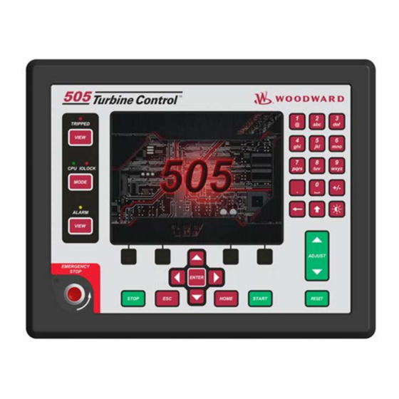
Page 28: Keypad And Display
Manual 35018V1 505XT Digital Control System for Steam Turbines Keypad and Display Graphical Display Key Inputs The front panel display is designed to provide the user with multiple levels of access for configuring, calibrating, tuning, operating, and monitoring the turbine operation. No additional control panels are required to operate the turbine, every turbine control function can be performed from the 505’s front... -
Page 29: Watchdog Timer/Cpu Fault Control
Manual 35018V1 505XT Digital Control System for Steam Turbines VIEW buttons will jump to the Trip or Alarm Summary screen to show these events in sequence with time stamp. MODE button will jump to a Login screen that allows the user to view current permissions and allow access to changing the user login level ESC Key –... -
Page 30: Chapter 2. Hardware Specifications
Flex505 Description and Features The Flex505 controller is a significant upgrade to the existing 505-product line with enhanced CPU, Graphical display, communications, and I/O functions. Note: This controller supports expanded I/O options when using Woodward CAN distributed I/O nodes. Features ... -
Page 31: Environmental Specifications
Calibration and Functional verification It is recommended to verify calibration and functional operation every 24-36 months. This is especially important for spare units that need to be ready for immediate use. Contact a Woodward Authorized Service Center for assistance. Aluminum Electrolytic capacitors It is recommended to apply power to spare units every 24-36 months for 3 hours to reform the electrolytic capacitors used in the power module. -
Page 32: Electromagnetic Compatibility (Emc)
If the display appears dim, use the “SCREEN SETTINGS” menu to verify the brightness setting and adjust as needed with the ADJ ARROW-BRIGHTNESS keypad combination. Contact a Woodward Authorize Service Center for a replacement display when damaged or if display quality is unacceptable. -
Page 33: Figure 2-2. 505D Outline Drawing
Manual 35018V1 505XT Digital Control System for Steam Turbines Figure 2-2. 505D Outline Drawing Woodward... -
Page 34: Input Power Specification
Manual 35018V1 505XT Digital Control System for Steam Turbines Input Power Specification Specifications (LV) LV Input Voltage range: 18-36 Vdc Input Power (max): < 77 W, 4.3 A max Output Voltage Holdup time: > 14 ms with 24 Vdc input voltage Isolation to other circuits: >... -
Page 35: Communications (Ethernet)
Manual 35018V1 505XT Digital Control System for Steam Turbines CPU OK indicator (green/red) This bi-color LED indicates the CPU status is operational (green) or faulty (red). The CPU will flash fault codes (red) if they exist. This LED exists on both the Front Panel and back cover. -
Page 36: Communications (Can)
Pin 8 – not used SHIELD = Chassis Network Configuration Utility (AppManager) Woodward's AppManager™ software can be used to configure network setting and load Control software (GAP), HMI display software (QT), and operating system service packs. The AppManager utility can be downloaded from www.woodward.com/software. -
Page 37: Table 2-3. Can Specifications
Max wire size: 1.3 mm² / 16 AWG for single wires, 0.5 mm² / 20 AWG for two wires CAN Cable Specifications Belden YR58684 (Woodward PN 2008-1512) communications / CAN cable is approved and recommended. This is a smaller and more flexible 0.3 mm² / 22 AWG, low capacitance cable suitable for tight routing in industrial environments. -
Page 38: Specifications
Flex500 / 505 hardware products. However, the shield must also be directly terminated to chassis (Earth) at one point in the network. In the case of Woodward equipment, the direct ground is meant to be located at the master device end, as it exits the master device’s enclosure. -
Page 39: Communications (Service Ports)
For debug use, a Woodward PN 5417-1344, USB to serial debug cable is required to attach this port to a PC. This port is to be used by trained Field Service personnel only! Table 2-7. -
Page 40: Hardware - Terminal Blocks & Wiring
Manual 35018V1 505XT Digital Control System for Steam Turbines Hardware - Terminal Blocks & Wiring Back cover view with wiring label. Figure 2-4. 505 Back Cover Label Woodward... -
Page 41: Terminal Block Connectors
Manual 35018V1 505XT Digital Control System for Steam Turbines Terminal Block Connectors Figure 2-5. Terminal Block Connectors Hardware - Speed Sensor Inputs This controller includes two (2) Digital Speed Sensor circuits that are capable of interfacing to MPU and Proximity speed probe sensors. Each channel is isolated from each other and may be configured for either MPU or PROX sensors. -
Page 42: Figure 2-6. Speed Sensor Block Diagram
Manual 35018V1 505XT Digital Control System for Steam Turbines Features Two (2) Digital Speed Sensor circuits, isolated individually GAP configurable for MPU sensors or Proximity sensor operation Separate terminals provided for MPU and Prox sensors Isolated Prox Power (+24 Vdc) is provided with short-circuit protection ... -
Page 43: Hardware - Analog Inputs (4-20 Ma)
Manual 35018V1 505XT Digital Control System for Steam Turbines Hardware - Analog Inputs (4-20 mA) AI Description and Features The Flex500 controller includes eight (8) 4–20 mA input channels for I/O monitoring and control. Each channel is differential (self-powered) but can be software configured for Loop Power mode. An Isolated Loop Power (+24 Vdc) is provided for analog input transducers and includes short-circuit/over-voltage protection. -
Page 44: Hardware - Analog Outputs (4-20 Ma)
Manual 35018V1 505XT Digital Control System for Steam Turbines Figure 2-8. Analog Input – Loop-Powered Block Diagram Hardware - Analog Outputs (4-20 mA) This control provides an isolated group of (6) 4-20 mA outputs for customer use. Each output can drive up to 600 ohm loads and provides fault monitoring of individual source and return currents. -
Page 45: Hardware - Actuator Outputs
Manual 35018V1 505XT Digital Control System for Steam Turbines Figure 2-9. Analog Output Block Diagram Hardware - Actuator Outputs This control provides an isolated group of two (2) Actuator outputs for customer use. Each driver can be configured for low-range (20 mA) or high-range (200 mA) operation. Fault monitoring of individual source and return currents is included. -
Page 46: Hardware - Discrete Inputs
Manual 35018V1 505XT Digital Control System for Steam Turbines Figure 2-10. Actuator Output Block Diagram Hardware - Discrete Inputs This control provides an isolated group of (20) discrete input channels for use with +24 V (dc) signals. An isolated Contact Power voltage supply of +24 V (dc) is provided to use with the discrete inputs. This supply includes short-circuit and over-voltage protection. -
Page 47: Hardware - Relay Outputs
Manual 35018V1 505XT Digital Control System for Steam Turbines Hardware - Relay Outputs This control provides (8) Isolated, Form-C Relay outputs with NO, COM, NC contacts available at the terminal block. Features • (8) Relay Output Channels • Each Relay Output provides NO, COM, and NC contacts •... -
Page 48: Troubleshooting Fault Codes
Verify PS(+) and PS(–) impedance to EARTH is > 10 MΩ RS-232 wiring checks Verify the RS-232 wiring uses a high quality shielded communication cable. For example, Woodward 2008-1512 (Belden YR58684) or equivalent low capacitance, shielded communications wire. ... - Page 49 CAN wiring checks Verify the CAN wiring uses a high quality, 3-wire, shielded communication cable. For example, Woodward 2008-1512 (Belden YR58684) or equivalent low capacitance, shielded communications wire. Verify CAN network length is < max length spec for the baud rate being used ...
- Page 50 Manual 35018V1 505XT Digital Control System for Steam Turbines DI, Contact Power (CPWR) wiring checks CPWR(+) is an output voltage, it should never be connected to any other supply. To maintain node isolation, verify CPWR(–) is not shorted to PS(–).
-
Page 51: Chapter 3. 505Xt Control Description
If the unit is a turbine type 1, 2, or 3, this is the point at which the 505XT will can be transitioned from speed control to ratio-limiter control. In ratio limiter control both the HP and LP valves are controlled to maintain 2 different parameters, selectable by the user. -
Page 52: Start Permissive
Zero Speed Signal Override The 505XT issues a shutdown if no speed signal is detected (magnetic pickup voltage less than 1 Vrms or speed is less than the ‘Failed Speed Level’). To allow the control to start with speed not being sensed, this shutdown logic must be overridden. -
Page 53: Direction Of Rotation Detection
Figure 3-2. Speed Probe mounting for Detection Test To enable the 505XT to calculate the direction of rotation – two speed signals must be used and should be mounted in an orientation as shown above, with approximately 90 degrees between them. This will work with both passive and active types of probes, however both channels must be configured as the same type of probe. -
Page 54: Detecting Zero Speed
Detecting Zero Speed To enable the 505XT to detect zero speed – an active speed probe signal must be used. The option to enable this detection feature is found on speed input channel 1. If a second active speed probe is used, the logic will require that the second probe also detects zero speed. -
Page 55: Automatic Speed Override
Service Mode). This time starts when the RUN command is initiated and re-arms the loss-of-speed detection when the time expires. The 505XT will execute a system shutdown if turbine speed is not above the ‘Failed Speed Level’ setting when the time expires. -
Page 56: Figure 3-5. Manual Start Mode Example
Manual 35018V1 505XT Digital Control System for Steam Turbines 2. Issue a START command (verify T&T valve is closed before issuing) a. At this point the 505 will ramp open the governor valve to its maximum position at the ‘Valve Limiter Rate’. -
Page 57: Figure 3-6. Semiautomatic Start Mode Example
Manual 35018V1 505XT Digital Control System for Steam Turbines Raise the 505’s VALVE LIMITER at a controlled rate. When turbine speed increases to the minimum controlling speed, the 505’s Speed PID will take control of turbine speed by controlling turbine inlet valve position. -
Page 58: Figure 3-7. Automatic Start Mode Example
These bands may be any speed range that is less than the minimum governor speed setting. Within a critical speed range, the 505XT moves the speed set point at the critical speed rate programmed and does not allow the speed set point to stop within the critical speed avoidance band. - Page 59 The 505XT will inhibit a ramp-to-idle speed or ramp-to-rated speed command, if the Generator Breaker is closed, Remote Speed Set Point is enabled, Cascade PID is in control, or the Auxiliary PID is in control (as defaulted in the Service Mode).
-
Page 60: Figure 3-8. Idle/Rated Start
Manual 35018V1 505XT Digital Control System for Steam Turbines If a 505 contact input is programmed to select between Idle or Rated speeds, Idle Speed is selected when the contact is open and rated speed is selected when it is closed. The Idle/Rated contact can be either open or closed when a trip condition is cleared. -
Page 61: Figure 3-9. Automatic Start Sequence
Manual 35018V1 505XT Digital Control System for Steam Turbines With this function, when a ‘START’ command is given: The Automatic Start Sequence ramps the speed set point to a low idle set point Holds at this setting for the set duration ... -
Page 62: Table 3-2. Hot And Cold Parameter Interpolation Rates And Delays
Manual 35018V1 505XT Digital Control System for Steam Turbines IDLE 2 SETPT 1500 USE IDLE 3 *TRUE RATE TO IDLE 3 (COLD) RPM/S RATE TO IDLE 3 (HOT) RPM/S IDLE 3 SETPT 2000 IDLE 3 DELAY TIME (COLD) MINIMUM IDLE 3 DELAY TIME (HOT) -
Page 63: Table 3-3. All Required Conditions, If Configured, For A Warm Or Hot Start
Manual 35018V1 505XT Digital Control System for Steam Turbines Hot/Cold Start Temperature Inputs An analog input configured as a temperature signal can be used to determine whether the turbine is hot or cold for startup speed setpoint rates and idle delay times. In addition, a warm setting is also available for a total of three turbine temperature conditions. - Page 64 Manual 35018V1 505XT Digital Control System for Steam Turbines Halting the Auto Start Sequence The Auto Start Sequence can be halted at any time from the 505 keypad, contact input or through Modbus. The sequence can be halted by a halt command, a raise or lower speed set point command, or when a speed set point is directly ‘Entered’...
-
Page 65: Speed Control Overview
Manual 35018V1 505XT Digital Control System for Steam Turbines If this option is programmed it will be use in one of the following ways: 1. It will provide a second unique setpoint relative to this temperature input for each idle speed level configured. -
Page 66: Speed Pid Operational Modes
Manual 35018V1 505XT Digital Control System for Steam Turbines Figure 3-10. Speed Control Functional Diagram Speed PID Operational Modes The Speed PID operates in one of the following modes, depending on configuration and system conditions: 1. Speed Control 2. Frequency Control 3. - Page 67 Manual 35018V1 505XT Digital Control System for Steam Turbines The Speed PID operates in the Frequency control mode when the generator breaker is closed and the utility tie breaker is open. In the Frequency control mode, the unit will operate at the same speed or frequency regardless of the load it is supplying (up to the unit’s load capability).
-
Page 68: Figure 3-11. Speed Pid Control Modes
Manual 35018V1 505XT Digital Control System for Steam Turbines Figure 3-11. Speed PID Control Modes The term “droop” was derived from an isolated unit’s speed reaction to an increase in load when another parameter (unit load) is fed back to a Speed PID’s summing junction. The Droop term, as used throughout this manual refers to a PID’s second controlling parameter. -
Page 69: Figure 3-12. Frequency And Unit Load Relationship
Manual 35018V1 505XT Digital Control System for Steam Turbines Figure 3-12. Frequency and Unit Load Relationship Because the 505’s Speed PID and set point are used to control turbine speed and a second parameter, this second parameter (unit load) is normalized to allow all three terms (speed, set point, unit load) to be summed together within the PID summing junction. - Page 70 Woodward Power Management product/device via a digital communication link (Woodward Links). To configure the 505 for turbine valve position control when paralleled to an infinite bus, uncheck the ‘Use KW Droop’ option. The generator load or turbine inlet valve position droop percentage cannot be set greater that 10%, and is typically set to 5%.
-
Page 71: Figure 3-13. Speed Relationships
Manual 35018V1 505XT Digital Control System for Steam Turbines Figure 3-13. Speed Relationships Once turbine speed is equal to or greater than the ‘Min Governor Speed Set Point’ setting, the speed set point may be adjusted through discrete raise and lower commands. When a raise or lower speed command is issued, the set point moves at the programmed ‘Speed Set Point Slow Rate’. - Page 72 Manual 35018V1 505XT Digital Control System for Steam Turbines When configured for generator applications a Minimum Load set point can be used by the 505 to reduce the chance of reverse powering a unit upon closing the generator breaker. With the utility tie breaker closed, when a generator breaker closed indication is received, the Speed set point is stepped to the Minimum Load setting.
-
Page 73: Table 3-4. Frequency Arm/Disarm Generator Control Modes
Manual 35018V1 505XT Digital Control System for Steam Turbines Table 3-4. Frequency Arm/Disarm Generator Control Modes Tie Breaker Gen Breaker Frequency Speed Initial Speed Cascade or Contact Contact Control Mode Reference Auxiliary Status Status (if used) closed open XXXX Speed, Off-... - Page 74 Manual 35018V1 505XT Digital Control System for Steam Turbines When configured an Extraction/Admition turbine, a third set of dynamics are optionally available when operating on the Ratio Limter. Initially, these value match and follow the On-Line dynamic settings. On the Speed Control Dynamics screen, the ‘Match On-Line’...
- Page 75 DSLC-2. The DSLC-2 product is the easiest to integrate with the 505 as it can be integrated via a digital communication connection by using the Woodward Links wizard. In some cases, the analog input signal interfaces described below are not required, but can be used as a redundant signal if desired.
- Page 76 Synchronizing/Load Sharing The 505 is capable of using an analog input to accept a load sharing signal from Woodward’s EGCP-3, easYgen or DSLC-2. The DSLC-2 product is the easiest to integrate with the 505 as it can be integrated via a digital communication connection by using the Woodward Links wizard.
-
Page 77: Figure 3-14. Load Sharing Logic
Manual 35018V1 505XT Digital Control System for Steam Turbines The ‘Sync/Ld Share Enable’ contact input option is used to enable the Sync/Load Share analog input before the generator breaker is closed. There is also a button on the speed Control screen that can be used to enable the 505’s Sync/Load Share analog input instead of an external contact. -
Page 78: Manual Demand
Manual 35018V1 505XT Digital Control System for Steam Turbines Table 3-6. Speed Control Mode Based on Contacts Tie Breaker Gen Breaker Sync/Ld Speed Initial Speed Cascade or Contact Contact Share Enable Control Mode Reference Auxiliary (if Status Status Contact used) -
Page 79: Load Rejection
If the 505XT Cascade controller is also controlling the compressor suction pressure, it will then respond to this pressure change, resulting in the two controllers temporarily affecting (fighting) each other. - Page 80 505XT Digital Control System for Steam Turbines The 505XT is capable of being configured to use an analog input (feed-forward signal) from an anti-surge controller. This input allows the 505XT controller to decouple the response of its Speed and Cascade PID controls from that of the anti-surge controller, allowing for increased system stability in all conditions.
-
Page 81: Cascade Control
Manual 35018V1 505XT Digital Control System for Steam Turbines Figure 3-15. Typical Anti-surge Valve and Speed Feed-Forward Logic Trend Cascade Control The Cascade control can be configured to control any system process, related to or affected by turbine speed or load. Typically this controller is configured and used as a turbine inlet, or exhaust pressure controller. -
Page 82: Figure 3-16. Cascade Functional Diagram
Manual 35018V1 505XT Digital Control System for Steam Turbines Figure 3-16. Cascade Functional Diagram Since Cascade is a secondary speed setting function, the Speed PID must be in control of the 505’s LSS bus in order for Cascade to take control. When the 505 is configured for a generator application, both the utility tie and generator breakers must be closed, before the Cascade PID can begin controlling a process. - Page 83 Manual 35018V1 505XT Digital Control System for Steam Turbines Cascade control is automatically disabled on a shutdown condition, and must be re-enabled after a successful system start-up. Cascade control is disabled if Remote Speed Set Point is used and enabled.
- Page 84 Manual 35018V1 505XT Digital Control System for Steam Turbines To “enter” a specific set point from the 505 Display use the following steps: 1. From the HOME page go to the Cascade Control page 2. Press the Commands button until ‘Entered Setpoint’ appears 3.
- Page 85 Manual 35018V1 505XT Digital Control System for Steam Turbines Remote Cascade Set Point If desired, the Cascade set point can be positioned through an analog signal. Optionally, one of the 505’s six analog inputs can be programmed to position the Cascade PID set point. This allows the Cascade set point to be positioned remotely by a process control or distributed plant control system.
-
Page 86: Auxiliary Control
Exhaust Steam Pressure Each of these inputs is a 4 to 20 mA current signal (the KW/Load could be from a ‘Woodward Links’ digital communication link). The PID control amplifier compares this input signal with the Auxiliary set point to produce a control output to the digital LSS (low-signal select) bus. The LSS bus sends the lowest signal to the actuator driver circuitry. - Page 87 Manual 35018V1 505XT Digital Control System for Steam Turbines Auxiliary as a Limiter (not using Enable/Disable) When configured as a limiter, the Auxiliary control is low signal selected (LSS) with all of the other PIDs, allowing it to limit turbine speed/load based on any auxiliary parameter which is directly related. To configure the Auxiliary controller to function as a limiter, do NOT check the configuration parameter of ‘Use Aux as Controller’.
- Page 88 Manual 35018V1 505XT Digital Control System for Steam Turbines Aux Control w/Rmt Setpt - Auxiliary is in control of the LSS bus and the remote Auxiliary analog input is in control of the set point. Auxiliary is Inhibited - Auxiliary cannot be enabled; input signal is failed, 505 is in Frequency Control, controlled shutdown is selected, unit is shut down or Auxiliary control is not programmed.
-
Page 89: Remote Auxiliary Set Point
Manual 35018V1 505XT Digital Control System for Steam Turbines Invert Auxiliary Input Depending on the control action required, the Auxiliary PID’s input signal can be inverted. If a decrease in inlet control valve position is required to increase the Auxiliary process signal, program the ‘INVERT AUX INPUT’... - Page 90 Manual 35018V1 505XT Digital Control System for Steam Turbines When enabled, the Remote Auxiliary Set Point may not match the Auxiliary set point. In this case, the Auxiliary set point will ramp to the Remote Auxiliary Set Point at the programmed ‘Aux Set Point Rate’...
-
Page 91: Extraction/Admission Control
Extraction control can be automatically or manually enabled and performed after one of the 505XT’s three starts have been accomplished, and any related extraction permissives have been met. All related Extraction enable permissives must be met before the control will allow the Extraction PID to take control of a process. - Page 92 Manual 35018V1 505XT Digital Control System for Steam Turbines 4. Open the Extr/Adm Trip-and-Throttle valve. 5. Enable Adm or Extr/Adm control. For full-decoupled configurations with Admission Only or Extraction/Admission turbines, the LP Valve Limiter will remain at 0% and must be manually increased after Admission or Extraction/Admission control has been enabled.
-
Page 93: Figure 3-19. Transitions Between Speed Only And Ratio Limiter Control - Auto Mode
Upon receiving a disable command, the 505XT will instantly step the LP valve limiter to the LP valve’s present position, then raise the LP limiter to its maximum (open) position at the “LP valve limiter rate”... -
Page 94: Figure 3-20. Transitions Between Speed Only And Ratio Limiter Control - Manual
Manual 35018V1 505XT Digital Control System for Steam Turbines Figure 3-20. Transitions Between Speed Only and Ratio Limiter Control – Manual Depending on the configuration and system conditions, the Ext/Adm controller may be in one of the following states: ... -
Page 95: Figure 3-21. Extraction/Admission Control Panel
Manual 35018V1 505XT Digital Control System for Steam Turbines Figure 3-21. Extraction/Admission Control Panel Manual P Control The output of the Ext/Adm controller that feeds into the Ratio Limiter logic is referred to as the P demand. Manual P control is a feature that allows the operator to take manual control of this value. The transition from Ext/Adm PID control into Manual P is always bumpless. - Page 96 Manual 35018V1 505XT Digital Control System for Steam Turbines LSS BUS OUTPUT % x ‘EXT/ADM DROOP %’ x ‘MAX SET POINT’ x 0.0001 Example: 25% x 5% x 600 psi x 0.0001 = 7.5 psi Where the ‘EXT/ADM DROOP %’ is set in Configuration mode, ‘MAX SET POINT’ value is determined by the upper range limit of the process variable selected and the ‘LSS bus output %’...
-
Page 97: Steam Performance Map Menu
Manual 35018V1 505XT Digital Control System for Steam Turbines The Remote Ext/Adm Set Point range is determined by the programmed Analog input’s 4 mA and 20 mA settings. The Remote Ext/Adm Set Point range is tunable in the Service mode, but cannot be set outside of the min and max Ext/Adm Set Point settings. - Page 98 Manual 35018V1 505XT Digital Control System for Steam Turbines The 505E uses the values programmed to calculate the turbine’s internal pressure ratios and limits. In order to get these values from your steam map, you must first check the following conditions and, if necessary, modify the map so it meets these conditions: ...
- Page 99 Manual 35018V1 505XT Digital Control System for Steam Turbines The eight values needed can be taken from the converted steam map. As an example, the following data was derived, using the above steam map in Figure 4-4. The MAX POWER value is the load where the S=100 line crosses the s-axis (about 20 000 kW in our example).
-
Page 100: Figure 3-22. Typical Extraction Steam Map
Manual 35018V1 505XT Digital Control System for Steam Turbines Figure 3-22. Typical Extraction Steam Map Admission Only Steam Map Before a turbine’s admission steam map can be programmed into the control, it must have the intersection points A, B, & C (refer to Figure 4-5). - Page 101 Manual 35018V1 505XT Digital Control System for Steam Turbines 4. Draw a line parallel to the LP=100 line, through the mark created in step 3. This will be your LP=0 line or LP valve closed line. 5. Mark the intersection of the P=100 and the LP=100 line. This will be Point C for programming.
-
Page 102: Figure 3-23. Typical Admission Steam Map
Manual 35018V1 505XT Digital Control System for Steam Turbines Figure 3-23. Typical Admission Steam Map Extraction & Admission Steam Map Before a turbine’s extraction/admission steam map can be programmed into the control, it must have the intersection points A, B, & C (refer to Figure 4-6). -
Page 103: Figure 3-24. Typical Extraction & Admission Steam Map
Manual 35018V1 505XT Digital Control System for Steam Turbines 1. Extend the maximum extraction line. Refer to Figure 4-6. 2. Extend the zero extraction & admission line. 3. Find your turbine’s minimum back-end steam flow (this will be point C’s HP flow). -
Page 104: Table 3-7. Alternate Modes For Ext/Adm Turbines
In simple terms the 505 has 2 control valves so therefore it can control 2 parameters as long as neither a parameter or a valve has reached a limit. Prior to configuring the 505XT control it is important to understand which parameters are planned to be controlled by the 505 for the specific plant/process steam turbine application. - Page 105 Ratio Limiter Functionality The 505XT Ratio/Limiter receives four input signals: Speed, Extraction, Inlet, and Exhaust demands. Only two of the inputs are used in control of the HP and LP valves at one time. The ratio logic uses these two active input signals to produce two output signals, one to control the HP actuator, and one to control the LP actuator.
- Page 106 Manual 35018V1 505XT Digital Control System for Steam Turbines This mode is used when the two controlled parameters during normal operation are turbine speed/load and extr/adm pressure (or flow). Mode 1: Speed and Inlet HP = D1.St + D2.Pt + D3 LP = D4.St + D5.Pt + D6...
- Page 107 Manual 35018V1 505XT Digital Control System for Steam Turbines This mode is used when the two controlled parameters during normal operation are inlet pressure (or flow) and extraction pressure (or flow). Mode 3: Speed and Exhaust HP = D1.St + D2.Pt + D3 [ 1 ] LP = D4.St + D5.Pt + D6...
- Page 108 Manual 35018V1 505XT Digital Control System for Steam Turbines Mode 5: Inlet and Exhaust (Decoupled) HP = D1.St + D2.Pt + D3 LP = D4.St + D5.Pt + D6 St = Q (Inlet) Pt = R (Exhaust) D1 = 1...
-
Page 109: Figure 3-32. Ext/Adm Mode Control Priorities
Manual 35018V1 505XT Digital Control System for Steam Turbines Figure 3-32. Ext/Adm Mode Control Priorities Fully Decoupled Mode – It is possible to run in a fully decoupled mode in which there is no interaction between the two PID’s and the two valve demand outputs. -
Page 110: Inlet Steam Pressure Control
Manual 35018V1 505XT Digital Control System for Steam Turbines Figure 3-33. Configured for Full Decoupled mode (No Map) Inlet Steam Pressure Control The Inlet Steam Pressure PID controller can be used to control the turbine inlet pressure, which is directly related to turbine speed/load. -
Page 111: Exhaust Steam Pressure Control
Manual 35018V1 505XT Digital Control System for Steam Turbines Inlet Pressure Control Functional Overview Inlet Steam Process Variable Input R/L Contact Inputs INVERT GUI Entry INLET INLET Setpoint Modbus Input Contact Input Remote SP Analog Input Feedback DROOP from LSS... -
Page 112: Hp Valve Limiter
Manual 35018V1 505XT Digital Control System for Steam Turbines Exhaust Pressure Control Functional Overview Exhaust Steam Process Variable Input R/L Contact Inputs INVERT GUI Entry EXHAUST EXHAUST Setpoint Modbus Input Contact Input Remote SP Analog Input Feedback DROOP from LSS... -
Page 113: Lp Valve Limiter
Manual 35018V1 505XT Digital Control System for Steam Turbines When a valid set point value is entered, the set point will ramp at the ‘Valve Limiter Rate’ to the newly entered set point value. This ‘Entered’ rate is tunable through the Service mode. -
Page 114: Inlet Steam Pressure Compensation
Manual 35018V1 505XT Digital Control System for Steam Turbines Use caution when adjusting manual demand as the 505 is no longer in control of any speed, load, or process. It is the responsibility of the operator to ensure safe operation of all processes related to valve movement. -
Page 115: Emergency Shutdown
Raise/Lower demand commands. These commands are available via Modbus, display, or contact inputs configured as Isolated PID raise/lower demand. Should a Process value be lost, it is also possible to configure the 505XT to hold the last value, ramp the PID output up or down automatically. -
Page 116: Controlled Shutdown
Manual 35018V1 505XT Digital Control System for Steam Turbines When programmed as a Trip relay, the respective relay will function like the dedicated Shutdown relay (normally energized and de-energizes on a shutdown) to indicate the position of the dedicated Shutdown relay. -
Page 117: Overspeed Test Function
Manual 35018V1 505XT Digital Control System for Steam Turbines Overspeed Test Function The 505’s Overspeed Test function allows an operator to increase turbine speed above its rated operating range to periodically test turbine electrical and/or mechanical overspeed protection logic and circuitry. -
Page 118: Table 3-8. Exceptions To Local Mode Contact Input And Modbus Command Disabled
Manual 35018V1 505XT Digital Control System for Steam Turbines Table 3-8. Exceptions to Local Mode Contact Input and Modbus Command Disabled External trip Contact In (defaulted in program) External trip 2 Contact In (active at all times, if programmed) External trip 3 Contact In... -
Page 119: Relays
Manual 35018V1 505XT Digital Control System for Steam Turbines Optionally a relay can be programmed to indicate when Local mode is selected (energizes when the Local mode is selected). There is also indication of the Local/Remote mode selection through Modbus (address = true when the Remote mode is selected and false = when the Local mode is selected). - Page 120 Manual 35018V1 505XT Digital Control System for Steam Turbines An Underspeed Switch function can be programmed to indicate a turbine underspeed or overpower condition. If the Underspeed option is configured, once turbine speed reaches a level above the minimum governor speed setting, then decreases 100 rpm below the minimum governor speed setting, the respective relay energizes (indicating an underspeed condition).
-
Page 121: Chapter 4. Configuration Procedures
Configuration Procedures Program Architecture The 505XT is easy to configure from the built-in graphical user interface (GUI). When the control is powered up and after the CPU self-test has been completed, the control displays the home screen and the CPU LED on the left side of the front panel should be green. At this point the configuration can be done locally on the display or remotely using the 505RemoteView tool on a user PC. -
Page 122: Configuring The 505Xt
Configuration menu parameters. Configuring the 505XT Before the 505XT can be used to operate any turbine, it must be configured with a valid configuration. A 505XT Configure Mode Worksheet is provided in Appendix A of this manual. This chapter contains additional information related to completing this worksheet and configuring the specific application. - Page 123 Manual 35018V1 505XT Digital Control System for Steam Turbines Use the following procedure to begin configuring the 505XT: 1. Press the MODE key. 2. Press the LOGIN softkey to open the User Login popup. 3. Login to the ‘Configure’ user level.
-
Page 124: Figure 4-2. Configuration Menu - Configuration Mode (Edit)
The configure menus are described in detail below and contain information detailing each question and/or 505XT configuration option. Each question/option shows the default (dflt) value and the adjustable range of that parameter (shown in parentheses). In addition, any additional constraints on the configuration are shown in italics following the description. - Page 125 Manual 35018V1 505XT Digital Control System for Steam Turbines Turbine Start Menu Start Mode: (One of the three start modes must be selected before the unit will run.) MANUAL START? dflt= NO (Yes/No) Select this to configure a manual start mode. When configured for a manual start mode, the operator controls the turbine speed from zero up to the minimum control speed using an external trip-throttle valve.
- Page 126 Manual 35018V1 505XT Digital Control System for Steam Turbines Hot Reset Timer (min) dflt= 0 (0.0, 200) Enter the reset LEVEL Setting. This is the time needed, when RST Timer level is reached, to transfer the start-up parameters from fully COLD to fully HOT.
- Page 127 Manual 35018V1 505XT Digital Control System for Steam Turbines RATED SETPOINT (rpm) dflt= 3600 (0.0, 20000) Enter the Rated Speed set point desired. This is the speed control set point that the unit accelerates to when using the Idle/Rated function.
- Page 128 Manual 35018V1 505XT Digital Control System for Steam Turbines IDLE 2 DELAY TIME—HOT (MINUTES) dflt= 1.0 (0.0, 500) Enter the hot start hold time desired at Idle 2. This is the programmable time, in minutes, that the turbine will wait/hold at the Idle 2 speed when a hot start is determined. If the turbine has been shutdown for longer than the Hot time but shorter than the Cold time, the control will interpolate between the Hot and Cold delays to determine the hi idle hold time.
- Page 129 Manual 35018V1 505XT Digital Control System for Steam Turbines MAX TEMPERATURE DIFFERENCE FOR IDLE 1 dflt= 1500.0 (0.0, 1.0e+38) Set the temperature difference that must be achieved for the automatic start sequence to continue through the Idle 1 speed setpoint based on the difference between temperature analog inputs 1 and 2.
- Page 130 Manual 35018V1 505XT Digital Control System for Steam Turbines AUTO HALT AT IDLE SETPOINTS? dflt= NO (Yes/No) Select YES to automatically halt the auto start sequence at the idle set points. This feature would result in the unit automatically stopping/halting at the low idle set point and at the high idle set point.
- Page 131 Manual 35018V1 505XT Digital Control System for Steam Turbines CRITICAL SPEED 2 MAX (rpm) dflt= 1.0 (1.0, 20000) Set the upper limit of the critical speed avoidance band. (Must be less than the ‘Minimum Governor Speed’ Setting) CRITICAL SPEED 2 MIN (rpm) dflt= 1.0 (1.0, 20000)
- Page 132 Manual 35018V1 505XT Digital Control System for Steam Turbines OFF-LINE PROPORTIONAL GAIN dflt= 5.0 (0.0, 100) Enter the off-line PID proportional gain percentage. This value is used to set speed/load control response when the Generator or Utility Tie breaker contacts are open (if the unit is a generator) or if the turbine speed is below minimum governor speed (if the unit is not a generator) or when the Select Dynamics function is used and the contact is open.
- Page 133 Manual 35018V1 505XT Digital Control System for Steam Turbines USE TIE BREAKER OPEN TRIP? dflt= NO (Yes/No) Select YES if opening the utility tie breaker is to initiate a turbine trip. If YES, the unit will trip when the utility tie breaker opens after being closed, unless a Controlled Stop is selected. If NO and the generator breaker is closed, the speed set point will instantly reset to the speed last seen by the unit and move to the ‘Rated Speed Set Point’...
- Page 134 Manual 35018V1 505XT Digital Control System for Steam Turbines DIRECT FEED-FORWARD? dflt = No (Yes/No) Set to YES if using the feed-forward loop as direct command followed by the ENTER. If YES is selected, the feed-forward speed bias will be directly proportional to the 4–20 mA signal.
- Page 135 Manual 35018V1 505XT Digital Control System for Steam Turbines FORWARD RATE TO ACTIVATE (%/s) dflt = 10(2,100) Set the minimum required rate of increase (%/s) to activate the emergency loop, followed by the ENTER. This is the rate at which the Feed-Forward analog input has to increase in order to trigger the Emergency Feed-Forward action.
- Page 136 Manual 35018V1 505XT Digital Control System for Steam Turbines PROCESS SIGNAL dflt= Auxiliary Input Select which input the control should use. The input selected here should be configured as an analog input, which is used as the process value for this controller.
- Page 137 Manual 35018V1 505XT Digital Control System for Steam Turbines Cascade Control Menu USE CASCADE CONTROL? dflt= NO (Yes/No) Select YES to configure the cascade control function. Select NO if the cascade function is not used. PROCESS SIGNAL dflt= Cascade Input Select which input the control should use.
- Page 138 Manual 35018V1 505XT Digital Control System for Steam Turbines REMOTE CASCADE MAX RATE (UNITS/s) dflt= 5.0 (0.1, 1000) Enter the maximum rate at which the remote input will move the cascade set point. UNITS OF MEASURE (Configured with Analog Inputs)
- Page 139 Manual 35018V1 505XT Digital Control System for Steam Turbines USE REMOTE SETPOINT ? dflt= NO (Yes/No) Set to YES to allow the set point to be adjusted from an analog input. (Must program a ‘remote inlet pressure set point’ analog input) REMOTE MAX RATE (UNITS/s) dflt= 5.0 (0.1, 1000)
- Page 140 Manual 35018V1 505XT Digital Control System for Steam Turbines GEN BREAKER OPEN EXT/ADM DISABLE ? dflt= YES (Yes/No) Select YES if the Ext/Adm pressure control will be disabled when the gen tie breaker opens. If NO is selected, then Ext/Adm pressure control will not be disabled when the gen breaker is opened.
- Page 141 Manual 35018V1 505XT Digital Control System for Steam Turbines PID INTEGRAL GAIN (%) dflt= 0.3 (0.001, 50) Enter the EXHAUST PID integral gain value. This value is used to set exhaust pressure control response. This value can be changed in the Run Mode while the turbine is operating. If unknown, a recommended starting value is 3%.
- Page 142 Manual 35018V1 505XT Digital Control System for Steam Turbines LOAD WHEN HP=100 (Min Flow Line) dflt= 100.0 (-100000.0, 100000.0) This is the load at HP=0% in engineering units. Extraction Priority on LP Max Limit? dflt= NO (YES/NO) Setting applies to Compressor applications only. When set to YES, the map priority will change from Speed to Extraction when the Max LP Limit is true.
- Page 143 Manual 35018V1 505XT Digital Control System for Steam Turbines K6 GAIN Map Value / Service Value dflt= 0.0 (-100, 100) Shows the calculated gain value from the entered steam map. Allows manual adjustment of this value if needed RETAIN SERVICE VALUES?
- Page 144 Manual 35018V1 505XT Digital Control System for Steam Turbines ENET 3 ADDRESS dflt= 192.168.129.20 (0, 255) Enter the integers corresponding to the network TCP/IP address. ENET 3 SUBNET MASK dflt= 255.255.255.0 (0, 255) Enter the integer corresponding to the network subnet mask.
- Page 145 Manual 35018V1 505XT Digital Control System for Steam Turbines Modbus Ethernet Link 3 ETHERNET Port 2 – IP Address = <display only> ETHERNET PROTOCOL dflt= TCP (TCP, UDP port 5001) Select TCP or UDP to determine the Ethernet communication protocol. Selecting UDP will use port 5002 for Link 3.
- Page 146 Manual 35018V1 505XT Digital Control System for Steam Turbines The Device Tag is a text field that is available for the user to enter a unique name or identifier for each I/O channel. An example would be to use the signal device tag such as PT-1234 for an Inlet Steam Pressure sensor.
- Page 147 Set the mA value that corresponds to 100% demand ACTUATOR 1 DITHER (%) dflt= 0.0 (0.0, 10) Enter the dither percentage for the actuator channel. Enter 0.0 if no dither is required. Woodward TM-type actuators typically require dither. USE ACTUATOR FAULT SHUTDOWN ? dflt= YES (Yes/No) Select YES to issue a trip whenever an actuator fault is detected.
- Page 148 Manual 35018V1 505XT Digital Control System for Steam Turbines CONTACT INPUT 01 FUNCTION Emergency Stop This channel is a dedicated trip input. DEVICE TAG This is a user entered field. It allows entry of a short description or tag name for this channel.
- Page 149 Relay outputs # 3 through # 8 are entered following the same rules as described for Relay output # 2. Woodward Links Menu The 505XT is able to easily interface with other Woodward product via a variety of digital communications links. This section allows the user to quickly configure the control to send and receive data from these devices.
- Page 150 Manual 35018V1 505XT Digital Control System for Steam Turbines The addition of vibration monitoring signals was designed to be done via the Vibration Wizard tool to help configure Vibration monitoring channels (1-8) on NODE 1. They must be done this way to have access to the gauge/monitoring screen for vibration that is available from the Startup Curve page, therefore it is recommended that all vibration sensors be connected to NODE 1.
-
Page 151: Exiting The Configure Mode
Manual 35018V1 505XT Digital Control System for Steam Turbines LINK TO VS-II (Digital valve positioner (DVP) on CAN Port 1) Enable the CAN 1 network interface Link? dflt= NO (Yes/No) Using a VariStroke II Actuator dflt= NO (Yes/No) DVP1 Device ID (1-31) -
Page 152: Table 4-3. Configuration Error Messages
If any errors are found in the program, the 505XT will remain in a shutdown state and a banner message will appear on the Configuration Menu and MODE screens. They can be displayed by pressing the ‘Config Check’ softkey on the Configuration Menu screen. - Page 153 Manual 35018V1 505XT Digital Control System for Steam Turbines Event Description Error Meaning Analog Input 01 Error The specified analog input was configured for a function that is not configured as used. Either the analog input was mis-configured or the function required is mis-configured. For example, analog input...
- Page 154 Manual 35018V1 505XT Digital Control System for Steam Turbines Event Description Error Meaning Actuator 01 Readout The Actuator/Driver channel readout was configured for a function Error that is not configured as used. Either the readout was mis- configured or the function required is mis-configured. For example, readout is configured for Cascade Set Point but Cascade Control was not configured under the Cascade Program Block.
- Page 155 Manual 35018V1 505XT Digital Control System for Steam Turbines Event Description Error Meaning KW CASC The Cascade control function was configured to use the kW Configured,CASC AI analog input but an Cascade analog input was configured also. Configured With this configuration, only the kW analog input is used for the Cascade controller.
- Page 156 Manual 35018V1 505XT Digital Control System for Steam Turbines Event Description Error Meaning Idle 2 Setpoint > The Idle Speed setpoint is configured at a higher speed than the Minimum Governor minimum governor speed setpoint. Idle 3 Setpoint > The Idle Speed setpoint is configured at a higher speed than the Minimum Governor minimum governor speed setpoint.
- Page 157 Manual 35018V1 505XT Digital Control System for Steam Turbines Event Description Error Meaning Maximum Speed > The maximum speed input is 35000 hertz. This is a limitation of Probe 1 Freq Range the 505’s hardware/speed sensing circuitry. The frequency input of the speed sensor must be less than this value.
- Page 158 Manual 35018V1 505XT Digital Control System for Steam Turbines Event Description Error Meaning SYNC LS Signal Source A controller has been configured to use a Synchronization/Load Not Selected Sharing input but no Primary or Secondary Signal source has been selected under Operating Parameters.
-
Page 159: Valve/Actuator Calibration & Test
Manual 35018V1 505XT Digital Control System for Steam Turbines Valve/Actuator Calibration & Test Before initial operation or after a turbine overhaul where any actuator or valve travel may have been affected, the below Valve Calibration procedure should be followed to insure that the 505 is correctly calibrated to the turbine control valve(s). - Page 160 Manual 35018V1 505XT Digital Control System for Steam Turbines 1. The 505 must be shutdown to enter Calibration Mode. 2. Go to the MODE screen by pressing the MODE key. 3. Enter Calibration Mode by pressing the ‘Calibration’ softkey. The following permissives must be met: a.
-
Page 161: Chapter 5. 505 Operation
505 Operation Software Architecture The 505XT is a field configurable steam turbine control and graphical user interface (GUI) integrated into one package. The 505XT control has been designed to run 2 separate, independent programs on the same platform. One controls the I/O and therefore controls turbine operation. The other program provides all the visual and command interaction with the user. -
Page 162: Figure 5-2. 505 Splash Screen
Manual 35018V1 505XT Digital Control System for Steam Turbines After about 1:15 TRIPPED=ON (RED) IOLOCK = OFF CPU = ON (GREEN) After about 1:50 ALARM LED (YELLOW) Flashes/Blinks After about 4:30 Screen = HOME Figure 5-2. 505 Splash Screen Any time that a Display application program is not running, the ‘Splash Screen’ will appear. If at power-up the Alarm LED stops flashing and this screen still appears –... -
Page 163: Control Mode Architecture
Manual 35018V1 505XT Digital Control System for Steam Turbines There is a Screen Saver function that is invoked after a period of inactivity. It is defaulted to 4 hours (adjustable in Service / Screen Settings) – when this comes it a small version of the ‘Splash Screen’ will bounce around on the screen. -
Page 164: User Login Levels
Manual 35018V1 505XT Digital Control System for Steam Turbines User Login Levels Pressing the MODE key at any time will open the Login and Mode Screen Figure 5-5. Mode Screen Monitor – (logout to enter this) Even Keypad Green keys inhibited Operator –... -
Page 165: Navigation
This is NOT a touchscreen! Due to quality, robustness, screen cleanliness and long term reliability concerns Woodward chose not to implement a touchscreen directly on this product. Using the RemoteView tool a user can take advantage of either a mouse device or a touchscreen on an external computer, but for navigation and selection directly on the 505 display, buttons and an IN-Focus highlighter indication are used. -
Page 166: Figure 5-8. Configuration Menu - Operation Mode (View Only)
Manual 35018V1 505XT Digital Control System for Steam Turbines Service menus - The Service ‘HOME’ page contains navigation buttons to all of the service related parameters and special feature of the control and it too is is automatically updated to match the configuration of the Configuration menus - The Configuration ‘HOME’... -
Page 167: Overview Screen
Overview Screen Figure 5-10. Overview Screen The Overview screen will adapt to the configuration of the 505XT and show all configured options. During normal run operation, this screen should provide the user with all of the primary turbine parameter values and operational status. -
Page 168: Valve Demand Screen
505XT Digital Control System for Steam Turbines The Speed Control screen will adapt to the configuration of the 505XT and show all configured options. During normal run operation, this screen provides the user with all details that are related to the turbine when operating in speed control. -
Page 169: Controllers Screen
Controllers Screen Figure 5-13. Controllers Screen The Controllers screen will adapt to the configuration of the 505XT and show all configured options. During normal run operation, this screen provides the user with information similar to the Overview, but in a graphical gauge view. It provides larger values for distance viewing and control PID information which is useful for monitoring when the 505 is near transition points between controllers or limiters. -
Page 170: Auxiliary Control Screen
Auxiliary Control Screen Figure 5-15. Auxiliary Control Screen The Auxiliary Control screen will adapt to the configuration of the 505XT. During normal run operation, this screen provides the user with all details that are related to the auxiliary control loop. The auxiliary control output goes to the LSS bus and can directly affect the HP valve demand output. -
Page 171: Extraction/Admission Control Screen
Extraction/Admission Control Screen Figure 5-17. Ext/Adm Pressure Control Screen The Extraction/Admission Control screen will adapt to the configuration of the 505XT. During normal run operation, this screen provides the user with all details that are related to the ext/adm control loop. The ext/adm control output goes into the Ratio Limiter control logic and will affect both the HP and LP valve demand outputs. -
Page 172: Exhaust Control Screen
Exhaust Control Screen Figure 5-18. Exhaust Pressure Control Screen The Exhaust Pressure Control screen will adapt to the configuration of the 505XT. During normal run operation, this screen provides the user with all details that are related to the exhaust pressure control loop. -
Page 173: Analog Input Summary Screen
Manual 35018V1 505XT Digital Control System for Steam Turbines The Steam Map Screen will be available for Extraction/Admission turbines. This page allows for real time viewing of the Operating Point within the steam map. This page can be used to adjust the Operating Point by manipulating the controller setpoints. -
Page 174: Contact Input Summary Screen
Manual 35018V1 505XT Digital Control System for Steam Turbines Contact Input Summary Screen Figure 5-22. Contact Input Summary Screen The Contact Input Summary screen will display the status of channels available on the 505 hardware. The fault status, function, and device tags are shown for each channel as well as navigation buttons for each channel that take the user to a page showing all parameters available for that input. -
Page 175: Relay Output Summary Screen
Manual 35018V1 505XT Digital Control System for Steam Turbines Relay Output Summary Screen Figure 5-24. Relay Output Summary Screen The Relay Output Summary screen will display the status of all channels available on the 505 hardware. The coil status, function, and device tag are shown for each channel as well as navigation buttons for each channel that take the user to a page showing all parameters available for that output. -
Page 176: Starting Procedures (Start Curve Screen)
Manual 35018V1 505XT Digital Control System for Steam Turbines Starting Procedures (Start Curve Screen) Figure 5-26. HOME Menu showing “Startup Curve” IN-Focus Refer to the turbine manufacturer’s operating procedures for complete information on turbine start up, and Chapter 3 of this manual for a step-by-step procedure, depending on the start mode selected. The... -
Page 177: Overspeed Test Function (Speed Control Screen)
Manual 35018V1 505XT Digital Control System for Steam Turbines Overspeed Test Function (Speed Control Screen) The 505’s Overspeed Test function allows an operator to increase turbine speed above its rated operating range to periodically test turbine electrical and/or mechanical overspeed protection logic and circuitry. -
Page 178: Figure 5-28. Internal (505) Overspeed Test
An external trip test is intended to be used to test the unit’s safety overspeed protection device (in many cases a Woodward ProTech). In this mode the 505 internal overspeed trip will be changed to be just an alarm and the 505 will allow the speed to continue increasing up to the Overspeed Test Limit (rpm). If the 505 speed OR the Setpoint reaches the Overspeed Test Limit it will TRIP ... -
Page 179: Stop Key
Manual 35018V1 505XT Digital Control System for Steam Turbines In the configuration of Speed Setpoints be sure that the Overspeed Test Limit rpm value is above the expected Overspeed setting of the external safety overspeed protection device. It is recommended to perform Overspeed Tests from these screens, either at the control (preferred) or via the RemoteView service tool. -
Page 180: Table 5-1. Alarm Messages
Manual 35018V1 505XT Digital Control System for Steam Turbines Each individual alarm condition is available through the Modbus links to monitor the control status. A common alarm indication is also provided. Relay indications can be programmed to indicate a 505 Common Alarm, in addition to the dedicated Alarm Relay output. - Page 181 Manual 35018V1 505XT Digital Control System for Steam Turbines Event DESCRIPTION MEANING IH-act1 Failed from BI Fault indication from current-to-hydraulic Actuator 1 (CPC) IH-act2 Failed from BI Fault indication from current-to-hydraulic Actuator 2 (CPC) HP Actuator Fault (Act1 or 2)
- Page 182 Manual 35018V1 505XT Digital Control System for Steam Turbines Event DESCRIPTION MEANING Actuator 3 Readout Fault Actuator Driver Chan 2 readback failure detected CAN1_DVP1 Summary ALM Summary Alarm from VariStroke device – Digital Valve Positioner 1 (DVP1) CAN1_DVP2 Summary ALM Summary Alarm from VariStroke device –...
-
Page 183: Shutdown Summary
Manual 35018V1 505XT Digital Control System for Steam Turbines Event DESCRIPTION MEANING Steam Map values entered will cause potentially unstable control in Alternate Mode Map Error an Alternate Mode. Verify correct sign on resulting D values LP Valve Pos Fdbk Diff ALM... - Page 184 Manual 35018V1 505XT Digital Control System for Steam Turbines Event DESCRIPTION MEANING Aux Input Failed Aux analog input failure detected (> 22 mA or < 2 mA) Power Up Trip 505 lost power or the Configuration mode was exited Normal Shutdown Complete...
-
Page 185: Manual Dynamic Adjustments Of Speed, Cascade, Auxiliary, Inlet, Exhaust And Ext/Adm Controls
Manual 35018V1 505XT Digital Control System for Steam Turbines Event DESCRIPTION MEANING 44 External Trip 14 External Trip #14 contact input was opened 45 External Trip 15 External Trip #15 contact input was opened 46 spare_46 reserved for future use... - Page 186 Manual 35018V1 505XT Digital Control System for Steam Turbines P = Proportional gain (%) I = Integral gain (%) D = Derivative (determined by DR and I) Tuning P & I Gains Proportional gain must be tuned to best respond to a system transient or step change. If system response is not known, a typical starting value is 5%.
- Page 187 Manual 35018V1 505XT Digital Control System for Steam Turbines For Extraction/Admission type turbines, there is a third set of dynamics that can be set to optimize operation within the steam performance map. These settings are identified as the ratio limiter dynamics and are only used when the unit is On-Line and Extraction/Admission control is enabled.
-
Page 188: Figure 5-33. Typical Response To Load Change
Manual 35018V1 505XT Digital Control System for Steam Turbines Figure 5-33 shows the typical response to a load change when the dynamics are optimally adjusted. Figure 5-33. Typical Response to Load Change For additional information on PID settings, refer to Volume 2. -
Page 189: Figure 5-34. Overview Of The Automated Pid Optimizer Routine
Manual 35018V1 505XT Digital Control System for Steam Turbines Figure 5-34. Overview of the Automated PID Optimizer Routine The Dynamics Optimizer screen is shown above. The current status is overviewed on the left hand side of the screen and results are given on the right. The menu bar on the bottom of the screen contains buttons which allow the configuration and operation of the Optimizer routine. -
Page 190: Figure 5-35. Optimization Routine Overview Trend
Manual 35018V1 505XT Digital Control System for Steam Turbines Figure 5-35. Optimization Routine Overview Trend Analysis Mode During the Analysis Mode, the optimizer begins by making small actuator movements which progressively increase until the measured process signal movement can be differentiated from signal noise. The initial movement direction (up or down) depends on system conditions. -
Page 191: Figure 5-36. Configuration Parameters 'Configure' Pop-Up
Manual 35018V1 505XT Digital Control System for Steam Turbines Once the routine is complete, the new gains can either be accepted by pressing the ‘Accept’ button within the Test Menu at the bottom of the screen. Alternatively, the gains can be rejected by pressing the ‘Reset Test’... - Page 192 Manual 35018V1 505XT Digital Control System for Steam Turbines Act Limit (online) (%) dflt= 10.0 (0.0, 100.0) This value limits how much the actuator demand will move during the Analysis Mode when the turbine is using Online dynamics. The percentage will limit the output +/- from the actuator position when the optimizer is enabled.
- Page 193 Manual 35018V1 505XT Digital Control System for Steam Turbines Most of the time, an alarm or fault indicates a problem with the steam turbine system that is outside of PID tuning. The descriptions below help identify what in the system may be causing the less than ideal control conditions.
- Page 194 Manual 35018V1 505XT Digital Control System for Steam Turbines Alarm 8 - Actuator movement is limited This alarm indicates that the actuator movement was limited during the Analysis Mode. This can result in a response that is not optimum, depending on the system conditions.
- Page 195 Manual 35018V1 505XT Digital Control System for Steam Turbines Faults Fault 1 – CLR_STATE was toggled TRUE This fault will only occur if the CLR_STATE input is toggled TRUE Some causes of this fault could be: The CLR_STATE input was toggled TRUE...
- Page 196 Manual 35018V1 505XT Digital Control System for Steam Turbines Fault 5 – Process movement greater than Process Limit This fault indicates that the process input exceed the Process Limit. Some causes of this fault could be: The Response Timeout is too long, the PID cannot increase the output movement fast enough to counteract system drift.
- Page 197 Manual 35018V1 505XT Digital Control System for Steam Turbines Some solutions for this fault would include: Decrease Response Timeout if the system is much faster than the time-out Check the Droop input for noise and for the correct level.
-
Page 198: Chapter 6. Communications
Manual 35018V1 505XT Digital Control System for Steam Turbines Chapter 6. Communications Modbus Communications The 505 control can communicate with plant distributed control systems and/or CRT based operator control panels through Modbus communication ports. There is one serial port that supports RS-232 and RS-485 communications using ASCII or RTU MODBUS transmission protocols. -
Page 199: Figure 6-1. Ascii/Rtu Representation Of 3
Service Mode, if required. The 505XT control is programmed to function as a slave unit only. As a slave unit, the 505XT will only respond to a transaction request by a master device. The 505 can directly communicate with a DCS or other Modbus supporting device on a single communications link, or through a multi-dropped network. -
Page 200: Table 6-2. Modbus Frame Definition
Manual 35018V1 505XT Digital Control System for Steam Turbines Table 6-2. Modbus Frame Definition Beginning Slave Function Data Error End of of Frame Address Code Check Frame Code 2 CHARS 2 CHARS 4 BITS 2 CHARS CR LF 8 BITS... -
Page 201: Port Adjustments
Manual 35018V1 505XT Digital Control System for Steam Turbines Port Adjustments Before the 505 will communicate with the master device, the communication parameters must be verified. These values are set in the Configure Mode and can be adjusted, if required, from the Service Mode. -
Page 202: Table 6-7. Boolean Write Addresses
Manual 35018V1 505XT Digital Control System for Steam Turbines Analog Reads (Input Registers) Input registers are analog values that are readable from, but not writable to, the 505 control. An example of an analog read value would be turbine speed. The values of the input registers are stored internal to the control as floating point numbers representing engineering units (kPa or rpm). -
Page 203: Table 6-8. Boolean Read Addresses
Manual 35018V1 505XT Digital Control System for Steam Turbines Addr Description Addr Description 0:0028 Disable Remote Cascade Setpoint 0:0083 Lower Inlet Setpoint Control 0:0029 Go To Modbus Entered Cascade Setpt 0:0084 Raise Inlet Setpoint 0:0030 Spare 0:0085 Enable Remote Inlet Setpoint Control... - Page 204 Manual 35018V1 505XT Digital Control System for Steam Turbines Addr Description Addr Description 1:0012 Alarm - HP Actuator Failed 1:0283 Alarm - HP2 Actuator Fault (DVP1 or 2) 1:0013 Alarm - HP2 Actuator Failed 1:0284 Alarm - Comm Link to DSLC2 Failed...
- Page 205 Manual 35018V1 505XT Digital Control System for Steam Turbines Addr Description Addr Description 1:0053 Trip - Tie Breaker Open 1:0324 Trip - Open Wire on MPUs 1:0054 Trip - Gen Breaker Open 1:0325 Trip - LP Actuator Failed 1:0055 Trip - Power up...
- Page 206 Manual 35018V1 505XT Digital Control System for Steam Turbines Addr Description Addr Description 1:0094 Sync or Load Share Is In Control 1:0365 Remote Extraction Configured 1:0095 Sync / Load Share Is Inhibitied 1:0366 Exhaust Is Enabled 1:0096 Spare 1:0367 Exhaust Is Active...
- Page 207 Manual 35018V1 505XT Digital Control System for Steam Turbines Addr Description Addr Description 1:0135 LP Valve Limiter Is Closed 1:0406 LinkNet Node 5: BO 05 1:0136 LP Valve Limiter In Control 1:0407 LinkNet Node 5: BO 06 1:0137 HP Valve Limiter Is Open...
- Page 208 Manual 35018V1 505XT Digital Control System for Steam Turbines Addr Description Addr Description 1:0176 Sync Function Configured 1:0447 LinkNet Node 2 AO_2 Fault 1:0177 Modbus- ESD Control Configured 1:0448 LinkNet Node 3 RTD_1 Fault 1:0178 Manual Start Configured 1:0449 LinkNet Node 3 RTD_2 Fault...
- Page 209 Manual 35018V1 505XT Digital Control System for Steam Turbines Addr Description Addr Description 1:0217 Alarm - Remote Droop fault 1:0488 LinkNet Node 3 RTD 1 Alarm Level 1 1:0218 Alarm - Hwr com1 fault 1:0489 LinkNet Node 3 RTD 1 Alarm Level 2...
-
Page 210: Table 6-9. Analog Read Addresses
Manual 35018V1 505XT Digital Control System for Steam Turbines Addr Description Addr Description 1:0258 Alarm - AO_04 Readback Fault 1:0529 Alarm - External alarm # 15 1:0259 Alarm - AO_05 Readback Fault 1:0530 Alarm - Alternate Mode Map Error 1:0260... - Page 211 Manual 35018V1 505XT Digital Control System for Steam Turbines Addr Description Units Multiplier 3:0032 Casc units AI_SCALE Remote Cascade Input (Scaled) 3:0033 aux units AI_SCALE Aux Setpoint (Scaled) 3:0034 Aux PID Output (%) x 100 3:0035 Aux Input (%) 3:0036...
- Page 212 Manual 35018V1 505XT Digital Control System for Steam Turbines Addr Description Units Multiplier 3:0084 Actuator #1 Output (mA x 100) 3:0085 Actuator #2 Output (mA x 100) 3:0086 Last Trip 3:0087 KW Units (3=MW 4=KW) 3:0088 Analog Input 1 Configuration...
- Page 213 Manual 35018V1 505XT Digital Control System for Steam Turbines Addr Description Units Multiplier 3:0136 * Droop Setting 3:0137 rpm/s * Autostart seq rate to Idle 1 3:0138 rpm/s * Autostart seq CF Cold rte to Idle 2 3:0139 rpm/s * Autostart seq CF Hot rate to Idle 2...
- Page 214 Manual 35018V1 505XT Digital Control System for Steam Turbines Addr Description Units Multiplier 3:0188 AI_SCALE Signal Monitoring #2 Input 3:0189 Signal Monitoring #3 Scale Factor 3:0190 AI_SCALE Signal Monitoring #3 Input 3:0191 Start Temperature 1 Scale Factor 3:0192 AI_SCALE Start Temperature 1 Input...
-
Page 215: Table 6-10. Analog Write Addresses
Master Modbus gathering this data. This will work, but those interfaces will not receive messages related to new features in the 505XT, it is a subset of the information available on the new addresses. -
Page 216: Table 6-12. Analog Read Register (3:0234) Control Status
Manual 35018V1 505XT Digital Control System for Steam Turbines Table 6-12. Analog Read Register (3:0234) Control Status Value Description Value Description Shutdown Auto Start Controlled Shutdown Semi Auto Start Transferring to Ratio Limiter Idle / Rated Start Control Transferring to Speed Only... -
Page 217: Table 6-14. Analog Read Register (3:0236) Map Limiter Status Messages
Manual 35018V1 505XT Digital Control System for Steam Turbines Table 6-14. Analog Read register (3:0236) Map Limiter Status Messages Value Description Value Description No Map Limits Map Limit - Min Flow & Min P - LP Limiter - Map Limit - Min Flow & Min LP - Map Limit - Min LP &... -
Page 218: Table 6-17. Analog Output Configuration
Manual 35018V1 505XT Digital Control System for Steam Turbines Table 6-16. Analog Input Configuration Value Description Description Value Signal Monitoring #3 --- Not Used --- Remote Speed Start Temperature 1 Setpoint Start Temperature 2 Synchronizing Input Extraction/Admission Input Sync / Load Share... -
Page 219: Table 6-18. Relay Configuration – For Level Switches
Manual 35018V1 505XT Digital Control System for Steam Turbines Signal Monitoring #2 Cascade Input Signal Signal Monitoring #3 Cascade Setpoint Start Temperature 1 Remote Cascade Setpoint Start Temperature 2 Auxiliary Input Signal LP Valve Demand Auxiliary Setpoint LP Valve Limiter Setpoint... -
Page 220: Table 6-19. Relay Configuration – For State Indications
Manual 35018V1 505XT Digital Control System for Steam Turbines Table 6-19. Relay Configuration – for State indications Value Value Description Description --- Not Used --- Cascade PID in Control Summary Shutdown Spare 42 Summary Shutdown (Trip Relay) Spare 43 Summary Alarm... -
Page 221: Table 6-20. Contact Input Configurations
Manual 35018V1 505XT Digital Control System for Steam Turbines Open GEN Breaker Cmd Spare_78 Feed-Forward Enabled Spare_79 Feed-Forward Active Spare_80 Analog Read addresses 3:0106—0117 give the configuration value of the contact inputs in order. The configuration for the contact inputs are defined in the table below. -
Page 222: Specific Address Information
Manual 35018V1 505XT Digital Control System for Steam Turbines Value Description Value Description External Trip 9 External Trip 12 External Trip 10 External Trip 13 External Alarm 1 External Trip 14 External Alarm 2 External Trip 15 External Alarm 3... - Page 223 Manual 35018V1 505XT Digital Control System for Steam Turbines Modbus Percentage Some of the analog read addresses have percentages sent across. The formula used in the percentage calculation is (actual/max) * 100). The percentage is multiplied by 100 before being sent across the Modbus to provide up to 2 decimal places, if desired.
-
Page 224: Chapter 7. Product Support And Service Options
An Authorized Independent Service Facility (AISF) provides authorized service that includes repairs, repair parts, and warranty service on Woodward's behalf. Service (not new unit sales) is an AISF's primary mission. A Recognized Turbine Retrofitter (RTR) is an independent company that does both steam and gas turbine control retrofits and upgrades globally, and can provide the full line of Woodward systems and components for the retrofits and overhauls, long term service contracts, emergency repairs, etc. -
Page 225: Returning Equipment For Repair
All repair work carries the standard Woodward service warranty (Woodward Product and Service Warranty 5-01-1205) on replaced parts and labor. -
Page 226: Replacement Parts
The unit serial number, which is also on the nameplate Engineering Services Woodward offers various Engineering Services for our products. For these services, you can contact us by telephone, by email, or through the Woodward website. Technical Support ... -
Page 227: Technical Assistance
505XT Digital Control System for Steam Turbines Technical Assistance If you need to contact technical assistance, you will need to provide the following information. Please write it down here before contacting the Engine OEM, the Packager, a Woodward Business Partner, or the Woodward factory: General... -
Page 228: Appendix A. 505Xt Configuration Mode Worksheets
Manual 35018V1 505XT Digital Control System for Steam Turbines Appendix A. 505XT Configuration Mode Worksheets Control Part Number ______________________ Serial Number ______________________ Application ________________________________ Date ___________ For details on individual settings, refer to Chapter 4. Site Default Value TURBINE START... - Page 229 Manual 35018V1 505XT Digital Control System for Steam Turbines Idle 3 Delay (Cold) Idle 3 Delay (Hot) Use Temp for Idle YES/NO Use Temp Input 2? YES/NO Use Temp Difference YES/NO Idle 1 Temp 1 Setpoint 1500 Temp deg Idle 1 Temp 2 Setpoint...
- Page 230 Manual 35018V1 505XT Digital Control System for Steam Turbines Probe Type Speed Sig 2 MPU/Active Device Tag ID User text Teeth Seen by MPU Gear Ratio 1 : 1.000 Max Speed Level (rpm) 1000 Failed Speed Level (rpm) Off-Line Prop Gain 5.000...
- Page 231 Manual 35018V1 505XT Digital Control System for Steam Turbines Aux PID Prop Gain 1.00 Aux PID Integral Gain 0.300 Aux Derivative Ratio Tiebrkr Open Aux Disable YES/NO Genbrkr Open Aux Disable YES/NO Use Remote Aux Setpoint YES/NO Remote Aux Max Rate...
- Page 232 Manual 35018V1 505XT Digital Control System for Steam Turbines Remote Inlet Max Rate Units/s Inlet Units of Measure User text Decimals Displayed value Site EXHAUST PRESSURE Default Value CONTROL Use Exhaust Pressure Control ? YES/NO Lost Exhaust Input Shutdown? YES/NO...
- Page 233 Manual 35018V1 505XT Digital Control System for Steam Turbines Site Default Value STEAM PERFORMANCE MAP Turbine Type single menu Maximum Power 20000 YES/NO Maximum HP Flow Units Use Alternate Modes? YES/NO Maximum Extraction Flow 20000 Units Maximum Admission Flow 20000...
- Page 234 Manual 35018V1 505XT Digital Control System for Steam Turbines Site Value Default COMMUNICATIONS Ethernet IP Configuration ENET 1 Address 172.16.100.15 ENET 1 Subnet Mask 255.255.0.0 ENET 2 Address 192.168.128.20 ENET 2 Subnet Mask 255.255.255.0 ENET 3 Address 192.168.129.20 ENET 3 Subnet Mask 255.255.255.0...
- Page 235 Manual 35018V1 505XT Digital Control System for Steam Turbines Discrete Input Channels - Function Invert Logic Emergency Stop Analog Output Channels - Function Val@4 Val@20 Units Rdbk Actuator Output Channels - Function Range mA@0 mA@100 Dither Act Flt = SD...
- Page 236 Manual 35018V1 505XT Digital Control System for Steam Turbines LinkNet I/O Modes – Channel Configuration Tables (OPTIONAL) Node 1 – 8 channels Analog Input 4-20mA & 2 channels Analog Output 4-20mA Function Val@4 Val@20 Units Modbus Mult. Disp Node 2 – 8 channels Analog Input 4-20mA & 2 channels Analog Output 4-20mA...
- Page 237 Manual 35018V1 505XT Digital Control System for Steam Turbines NODE 2 Events Level 1 Level Setpoint Delay Alm1 Alm2 Trip 2 SP Hysteresis NODE 3 Events Level 1 Level Setpoint Delay Alm1 Alm2 Trip 2 SP Hysteresis Node 4 – 16 channel Discrete Input (24Vdc)
- Page 238 Manual 35018V1 505XT Digital Control System for Steam Turbines Node 5 – 16 channel Discrete Output (24Vdc) Level or Function Invert Level ON Level OFF State Logic When Actuator Outputs have been (In Service) Calibrated and Stroked, record values here.
-
Page 239: Revision History
Manual 35018V1 505XT Digital Control System for Steam Turbines Revision History Changes in Revision B— Automated PID Dynamic Optimizer added to Chapter 5 Compliance updates and updated DOC Changes in Revision A— New content on pg. 26 immediately below Fig. 1-9 ... -
Page 240: D Eclarations
Manual 35018V1 505XT Digital Control System for Steam Turbines Declarations Woodward... - Page 241 Manual 35018V1 505XT Digital Control System for Steam Turbines Woodward...
- Page 242 Email and Website—www.woodward.com Woodward has company-owned plants, subsidiaries, and branches, as well as authorized distributors and other authorized service and sales facilities throughout the world. Complete address / phone / fax / email information for all locations is available on our website.
Need help?
Do you have a question about the 505XT and is the answer not in the manual?
Questions and answers