
Related Manuals for MICRO-EPSILON thermoMETER CTL Series


Summary of Contents for MICRO-EPSILON thermoMETER CTL Series
- Page 1 Operating Instructions thermoMETER CTLM-1 CTLC CTLF CTLM-2 CTLG CTLM-3 CTLM-5...
- Page 2 Infrared sensor MICRO-EPSILON MESSTECHNIK GmbH & Co. KG Koenigbacher Str. 15 94496 Ortenburg / Germany Tel. +49 (0) 8542 / 168-0 Fax +49 (0) 8542 / 168-90 e-mail info@micro-epsilon.com www.micro-epsilon.com...
-
Page 3: Table Of Contents
Contents Safety ............................7 Symbols Used ..............................7 Warnings ................................7 Notes on CE Marking ............................8 Intended Use ..............................9 Proper Environment ............................9 Laser Safety ..........................10 Technical Data ........................12 Functional Principle ............................12 Sensor Models ............................... 13 General Specifications ........................... - Page 4 Electrical Installation ......................40 Cable Connections ............................40 7.1.1 Basic Version ..........................40 7.1.2 Connector Version ........................40 Power Supply ..............................44 Cable Assembling ............................45 Ground Connection ............................46 7.4.1 CTLM-5, CTLM-1, CTLM-2, CTLM-3L, CTLM-3H, CTLM-3H1 to -3H3 Models ......46 7.4.2 CTL, CTLF, CTLC-4, CTLC-2, CTLC-6, CTLG Models ..............
- Page 5 8.2.7 Ethernet Interface ......................... 66 8.2.7.1 Installation ........................66 8.2.7.2 Installation of the Ethernet Adapter in a Network ............67 8.2.7.3 Deinstallation of an Ethernet Interface in a Network ..........68 8.2.7.4 Direct Connection to a PC ..................71 8.2.7.5 Settings inside the CompactConnect Software ............
- Page 6 Emissivity ..........................95 14.1 Definition ................................ 95 14.2 Determination of Unknown Emissivity ......................95 14.3 Characteristic Emissivity ..........................96 Liability for Material Defects ....................97 Service, Repair ........................98 Decommissioning, Disposal ....................98 Appendix Optional Accessories ......................99 A 1.1 Air Purge Collar ..............................
-
Page 7: Safety
Safety Safety System operation assumes knowledge of the operating instructions. Symbols Used The following symbols are used in these operating instructions. Indicates a hazardous situation which, if not avoided, may result in minor or moder- ate injury. Indicates a situation that may result in property damage if not avoided. Indicates a user action. -
Page 8: Notes On Ce Marking
Products which carry the CE mark satisfy the requirements of the EU directives cited and the European harmonized standards (EN) listed therein. The EU Declaration of conformity is available to the responsible authorities according to the EU Directive, article 10, at: MICRO-EPSILON MESSTECHNIK GmbH & Co. KG Koenigbacher Str. 15 94496 Ortenburg / Germany The measuring system is designed for use in industrial environments and meets the requirements. -
Page 9: Intended Use
Safety Intended Use - The thermoMETER CTL is designed for use in industrial and laboratory areas. It is used for non-contact temperature measurement. - The system must only be operated within the limits specified in the technical data, see 3. - The system must be used in such a way that no persons are endangered or machines and other material goods are damaged in the event of malfunction or total failure of the sensor. -
Page 10: Laser Safety
Laser Safety Laser Safety The thermoMETER CTL sensors operate with a double laser sight with a wavelength of 635 nm (visible/red), 9.4. The sensors fall within laser class 2 (II). The maximum optical power is ≤ 1 mW. Observe the laser protection regulations! Although the laser output is low, directly looking into the laser beam must be avoided. - Page 11 Laser Safety Fig. 2 Controller with laser labels If the warning label is covered over when the unit is installed, the user must ensure that supplementary label is applied. thermoMETER CTL Page 11...
-
Page 12: Technical Data
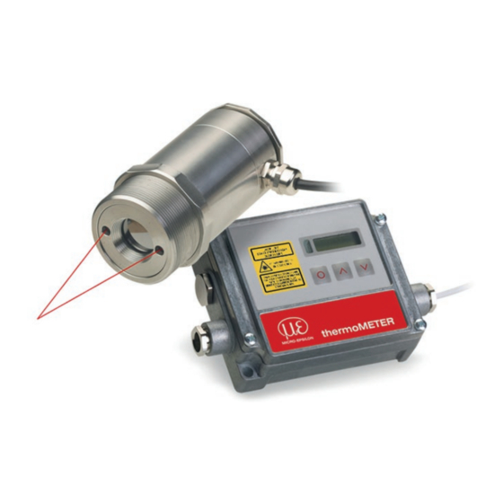
Technical Data Functional Principle The sensors of the thermoMETER CTL series are non-contact measuring infrared temperature sensors. They calculate the surface temperature based on the emitted infrared energy of objects, see Chap. 12. An inte- grated double laser aiming marks the real measurement spot location and spot size at any distance on the object surface. -
Page 13: Sensor Models
Technical Data Sensor Models Model Model codes Spectral response Typical applications -50 to 975 °C 8 - 14 μm Non-metallic surfaces CTLF -50 to 975 °C 8 - 14 μm Fast processes CTLM-1 485 to 2200 °C 1 μm Metals and ceramic surfaces CTLM-2 250 to 2000 °C 1.6 μm... -
Page 14: General Specifications
Technical Data General Specifications Sensor Controller Protection class IP 65 (NEMA-4) Ambient temperature -20 ... +85 °C (-4 ... +185 °F) (-20) 0 ... +85 °C -4 (+32 °F ... +185 °F) Storage temperature -40 ... +85 °C (-4 ... +185 °F) Relative humidity 10 ... -
Page 15: Electrical Specifications
Technical Data Electrical Specifications Power supply 8 – 36 VDC Power consumption Max. 160 mA Aiming laser 635 nm, 1 mW, On/ Off via programming keys or software Channel 1 Selectable: 0/ 4 – 20 mA, 0 – 5/ 10 V, thermocouple (J or K) or alarm output (signal source: Object temperature Channel 2 Sensor temperature [-20 ... -
Page 16: Measurement Specifications
Technical Data Measurement Specifications 3.5.1 CTL, CTLF Models Model CTLF Temperature range (scalable) -50 ... 975 °C Spectral range 8 ... 14 μm Optical resolution 75:1 50:1 System accuracy ±1 °C or ±1 % ±1,5 °C or ±1,5 % Repeatability ±0.5 °C or ±0.5 % ±1 °C or ±1 % Temperature resolution (NETD) -
Page 17: Ctlm-1 And Ctlm-2 Models
Technical Data 3.5.2 CTLM-1 and CTLM-2 Models Model M-1L M-1H M-1H1 M-2L M-2H M-2H1 Temperature range (scalable) 485/1050 °C 650/1800 °C 800/2200 °C 250/800 °C 385/1600 °C 490/2000 °C Spectral range 1 μm 1.6 μm Optical resolution 150:1 300:1 150:1 300:1 System accuracy ±(0.3 % T of reading +2 °C) -
Page 18: Ctlm-3 Models
Technical Data 3.5.3 CTLM-3 Models Model M-3L M-3H M-3H1 M-3H2 M-3H3 Temperature range (scalable) 50/400 °C 100/600 °C 150/1000 °C 200/1500 °C 250/1800 °C 2.3 μm Spectral range 60:1 100:1 300:1 Optical resolution System accuracy ±(0.3 % of reading +2 °C) ±(0.1 % of reading +1 °C) Repeatability Temperature resolution (digital) -
Page 19: Ctlm-5 Model
Technical Data 3.5.4 CTLM-5 Model Model Temperature range 1000/2000 °C Spectral range 525 nm Optical resolution 150:1 System accuracy ±(0.3 % of reading +2 °C) Repeatability ±(0.1 % of reading +1 °C) Temperature resolution 0.2 °C Response time (90 % signal) 1 ms Emissivity/ gain 0.100…1.100... -
Page 20: Ctlc Models
Technical Data 3.5.5 CTLC Models Model Temperature range 200/1450 °C Spectral range 4.24 μm 3.9 μm 4.64 μm Optical resolution 45:1 System accuracy ±1 % 3 4 5 Repeatability ±0.5 % or ±0.5 °C Temperature resolution (digital) 0.1 °C Response time (90 % signal) 10 ms Emissivity/ gain 0.100…1.100... -
Page 21: Ctlg Models
Technical Data 3.5.6 CTLG Models Model GF-H Temperature range 100 ... 1200 °C 250 ... 1650 °C 200 ... 1450 °C Spectral range 5.0 μm Optical resolution 45:1 70:1 45:1 System accuracy ±1 °C or ±1.5 % Repeatability ±0.5 °C or ±0.5 % Temperature range (NETD) 0.1 °C Exposure time (90 % signal) -
Page 22: Delivery
Delivery Delivery Unpacking, Included in Delivery 1 thermoMETER CTL sensor 1 Controller 1 Sensor cable 1 Mounting nut and mounting bracket (fixed) 1 Operating instructions Carefully remove the components of the measuring system from the packaging and ensure that the goods are forwarded in such a way that no damage can occur. -
Page 23: Optical Charts
Optical Charts Optical Charts The following optical charts show the diameter of the measuring spot in dependence on the distance between measuring object and sensor. The spot size refers to 90 % of the radiation energy. The distance is always measured from the front edge of the sensor. The size of the measuring object and the optical resolution of the infrared thermometer determine the maximum distance between sensor and measuring object. - Page 24 Optical Charts Optics: SF D:S (Focus distance) = 75:1 16 mm @ 1200 mm D:S (Far field) = 24:1 Optics: CF1 D:S (Focus distance) = 75:1 0.9 mm @ 70 mm D:S (Far field) = 3.5:1 thermoMETER CTL Page 24...
- Page 25 Optical Charts Optics: CF2 D:S (Focus distance) = 75:1 1.9 mm @ 150 mm D:S (Far field) = 7:1 Optics: CF3 D:S (Focus distance) = 75:1 2.75 mm @ 200 mm D:S (Far field) = 9:1 thermoMETER CTL Page 25...
- Page 26 Optical Charts Optics: CF4 D:S (Focus distance) = 75:1 5.9 mm @ 450 mm D:S (Far field) = 18:1 CTLF Optics: SF D:S (Focus distance) = 50:1 24 mm @ 1200 mm D:S (Far field) = 20:1 thermoMETER CTL Page 26...
- Page 27 Optical Charts CTLF Optics: CF1 D:S (Focus distance) = 50:1 1.4 mm @ 70 mm D:S (Far field) = 3.5:1 CTLF Optics: CF2 D:S (Focus distance) = 50:1 3 mm @ 150 mm D:S (Far field) = 6:1 thermoMETER CTL Page 27...
- Page 28 Optical Charts CTLF Optics: CF3 D:S (Focus distance) = 50:1 4 mm @ 200 mm D:S (Far field) = 8:1 CTLF Optics: CF4 D:S (Focus distance) = 50:1 9 mm @ 450 mm D:S (Far field) = 16:1 thermoMETER CTL Page 28...
- Page 29 Optical Charts M-1H/ M-1H1/ M-2H/ M-2H1/ M-3H1/ M-3H2/ M-3H3 Optics: FF D:S (Focus distance) = 300:1 12 mm @ 3600 mm D:S (Far field) = 115:1 M-1L/ M-2L / M-5-1L/ M-5-2L Optics: FF D:S (Focus distance) = 150:1 24 mm @ 3600 mm D:S (Far field) = 150:1 M-1H/ M-1H1/ M-2H/ M-2H1/ M-3H1/ M-3H2/ M-3H3...
- Page 30 Optical Charts M-1H/ M-1H1/ M-2H/ M-2H1/ M-3H1/ M-3H2/ M3-H3 Optics: CF2 D:S (Focus distance) = 300:1 0.5 mm @ 150 mm D:S (Far field) = 7.5:1 M-1L/ M-2L Optics: CF2 D:S (Focus distance) = 150:1 1 mm @ 150 mm D:S (Far field) = 7:1 M-1H/ M-1H1/ M-2H/ M-2H1/ M-3H1/ M-3H2/ M3-H3...
- Page 31 Optical Charts M-1H/ M-1H1/ M-2H/ M-2H1/ M-3H1/ M-3H2/ M3-H3 Optics: CF4 D:S (Focus distance) = 300:1 1.5 mm @ 450 mm D:S (Far field) = 22:1 M-1L/ M-2L Optics: CF4 D:S (Focus distance) = 150:1 3 mm @ 450 mm D:S (Far field) = 20:1 M-3H Optics: SF...
- Page 32 Optical Charts M-3H Optics: CF1 D:S (Focus distance) = 100:1 0,85 mm @ 85 mm D:S (Far field) = 3:1 M-3L Optics: CF1 D:S (Focus distance) = 60:1 1.4 mm @ 85 mm D:S (Far field) = 3:1 M-3H Optics: CF2 D:S (Focus distance) = 100:1 1.5 mm @ 150 mm D:S (Far field) = 7:1...
- Page 33 Optical Charts M-3H Optics: CF3 D:S (Focus distance) = 100:1 2 mm @ 200 mm D:S (Far field) = 9:1 M-3L Optics: CF3 D:S (Focus distance) = 60:1 3.4 mm @ 200 mm D:S (Far field) = 8:1 M-3H Optics: CF4 D:S (Focus distance) = 100:1 4.5 mm @ 450 mm D:S (Far field) = 19:1...
- Page 34 Optical Charts GL / CTLC-4 / CTLC-2 / CTLC-6 Optics: SF D:S (Focus distance) = 45:1 27 mm @ 1200 mm D:S (Far field) = 25:1 Optics: SF D:S (Focus distance) = 70:1 17 mm @ 1200 mm D:S (Far field) = 33:1 GL / CTLC-4 / CTLC-2 / CTLC-6 Optics: CF1...
- Page 35 Optical Charts GL / CTLC-4 / CTLC-2 / CTLC-6 Optics: CF2 D:S (Focus distance) = 45:1 3.4 mm @ 150 mm D:S (Far field) = 6:1 Optics: CF2 D:S (Focus distance) = 70:1 2.2 mm @ 150 mm D:S (Far field) = 6.8:1 GL / CTLC-4 / CTLC-2 / CTLC-6 Optics: CF3...
- Page 36 Optical Charts GL / CTLC-4 / CTLC-2 / CTLC-6 Optics: CF4 D:S (Focus distance) = 45:1 10 mm @ 450 mm D:S (Far field) = 15:1 Optics: CF4 D:S (Focus distance) = 70:1 6,5 mm @ 450 mm D:S (Far field) = 17.7:1 thermoMETER CTL Page 36...
-
Page 37: Mechanical Installation
Mechanical Installation Mechanical Installation Sensor Keep the optical path free of any obstacles. For an exact alignment of the sensor to the object activate the integrated double laser, see 9.4. The CTL is equipped with a metric M48x1.5 thread and can be installed either directly via the sensor thread or with help of the supplied mounting nut (standard) and fixed mounting bracket (standard) to a mounting device available. -
Page 38: Controller
Mechanical Installation Controller 110 (4.33) 22 (.87) 92 (3.62) 4 (.16) 13 (.51) M12x1.5 89 (3.50) (.51) (1.18) (.16) max. 120 (4.72) Fig. 4 Dimensions CTL controller Dimensions in mm, not to scale thermoMETER CTL Page 38... -
Page 39: Mounting Bracket
Mechanical Installation Mounting Bracket The mounting bracket is included in delivery, see 4.1. 46.27 4 (.16) (1.82) (2.24) 49 (1.93) 60 (2.36) Fig. 5 Dimensions mounting bracket, fixed Dimensions in mm, not to scale The adjustable mounting bracket allows an adjustment of the sensor in two axis. thermoMETER CTL Page 39... -
Page 40: Electrical Installation
Electrical Installation Electrical Installation Cable Connections 7.1.1 Basic Version The basic version is supplied with a sensor cable (connection sensor - controller). For the electrical installation of the CTL please open at first the cover of the controller (4 screws). Below the display are the screw terminals for the cable connection. - Page 41 Electrical Installation Pin assignment of connector plug (connector version only) Designation Color (original sensor cable) Detector signal (+) yellow Temperature sensor brown Temperature sensor white Detector signal (-) green Ground laser (-) grey Power supply laser (+) pink not used Connector plug (outer view) Fig.
- Page 42 Electrical Installation Designation (Models CTL/ CTLF/ CTLC/ CTLG) +8 ... 36 VDC Power supply Ground (0 V) of power supply Ground (0 V) of internal inputs and outputs OUT-AMB Analog output sensor temperature (mV) OUT-TC Analog output thermocouple (J or K) OUT-mV/mA Analog output object temperature (mV or mA) F1-F3...
- Page 43 Electrical Installation Designation (Models CTLM) +8 ... 36 VDC Power supply Ground (0 V) of power supply Ground (0 V) of internal inputs and outputs Alarm 2 (open-collector output) OUT-TC Analog output thermocouple (J or K) OUT-mV/mA Analog output object temperature (mV or mA) F1-F3 Functional inputs Ground (0 V)
-
Page 44: Power Supply
Electrical Installation Power Supply Please use a power supply unit with an output voltage of 8 - 36 VDC that provides at least 160 mA cur- rent. Residual ripple should be no more than 200 mV. Never apply voltage to the analog outputs. >... -
Page 45: Cable Assembling
Electrical Installation Cable Assembling The cable gland M12x1.5 allows the use of cables with a diameter of 3 to 5 mm. Remove the isolation from the cable (40 mm power supply, 50 mm signal outputs, 60 mm functional inputs). Cut the shield down to approximately 5 mm and spread the strands out. Extract about 4 mm of the wire isolation and tin the wire ends. -
Page 46: Ground Connection
Electrical Installation Ground Connection 7.4.1 CTLM-5, CTLM-1, CTLM-2, CTLM-3L, CTLM-3H, CTLM-3H1 to -3H3 Models At the bottom side of the main board PCB you will find a connector (jumper), which has been placed from factory side as shown in the picture (lower and middle pin connected), see Fig. -
Page 47: Ctl, Ctlf, Ctlc-4, Ctlc-2, Ctlc-6, Ctlg Models
Electrical Installation 7.4.2 CTL, CTLF, CTLC-4, CTLC-2, CTLC-6, CTLG Models At the bottom side of the main board PCB you will find a connector (jumper), which has been placed from factory side as shown in the picture (left and middle pin connected), see Fig. -
Page 48: Exchange Of The Sensor
Electrical Installation Exchange of the Sensor After exchanging a head the calibration code of the new sensor must be entered into the controller. After modification of the code a reset is necessary to activate the changes, see The calibration code is fixed on a label on the sensor. Do not remove this label or note the code. The code is needed if the controller must be exchanged. -
Page 49: Entering Of The Calibration Code
Electrical Installation 7.5.1 Entering of the Calibration Code Every sensor has a specific calibration code, that is clearly printed on a label on the sensor, see Fig. 14. Fig. 14 Calibration code Please do not remove this label or make sure the code is noted anywhere. The code is needed if the sensor has to be exchanged. -
Page 50: Exchange Of The Sensor Cable
Electrical Installation 7.5.2 Exchange of the Sensor Cable The sensor cable can also be exchanged if necessary. For a dismantling on the sensor side, please open at first the cover plate on the back side of the sensor. Then please remove the terminal block and loose the connections. After the new cable has been installed, please do the same steps in reverse order. -
Page 51: Outputs And Inputs
Outputs and Inputs Outputs and Inputs Analog Outputs The thermoMETER CTL has two analog output channels. 8.1.1 Output Channel 1 This output is used for the object temperature. The selection of the output signal can be done via the pro- gramming keys, see 9. -
Page 52: Digital Interfaces
Outputs and Inputs Digital Interfaces All CTL sensors can be optionally equipped with an USB-, RS232-, RS485-, CAN Bus-, Profibus DP- or Ethernet-interface. In the case that you want to use the delivered cable gland M12x1.5 for the interface cable, please disassem- ble the terminal block and assemble them again. -
Page 53: Usb Interface
Outputs and Inputs 8.2.1 USB Interface 8.2.1.1 Installation Mount the USB adapter, see 8.2. Make sure the wiring is correct according to the wire colors printed on the interface board. For industrial installations it is recommended to connect the shield of the USB adapter cable with the control- ler housing (inside the cable gland). -
Page 54: Rs232 Interface
Outputs and Inputs 8.2.2 RS232 Interface 8.2.2.1 Installation Mount the RS232 adapter, see 8.2. Make sure the wiring is correct according to the drawing and designation printed on the interface board, see Fig. 17. The CTL always needs an external power supply for operation. 8.2.2.2 Software Installation Please install the CompactConnect software, see... -
Page 55: Rs485 Interface
Outputs and Inputs 8.2.3 RS485 Interface 8.2.3.1 Installation Mount the RS485 adapter, see 8.2. The RS485-USB adapter is providing a 2-wire half-duplex mode. Please connect terminal A of the interface with terminal A of the next RS485 interface and so on, see Fig. -
Page 56: Sensor Installation
Outputs and Inputs 8.2.3.2 Sensor Installation Each CTL unit connected to the RS485 needs a different multidrop address (1 ... 32). button until M xx appears in the display. Please adjust the address by pressing the Using the Up and Down keys you can change the shown address (xx) The address can also be changed with the CompactConnect software. -
Page 57: Profibus Interface
Outputs and Inputs 8.2.4 Profibus Interface 8.2.4.1 Installation Mount the Profibus adapter, see 8.2. Make sure the wiring is correct, see Fig. 19. We recommend for industrial installations to connect the shield of the Profibus cable with the controller housing (inside the cable gland). The thermoMETER CTL always needs an external power supply. -
Page 58: Commissioning Profibus
Outputs and Inputs 8.2.4.2 Commissioning Profibus Read in the „IT010A90.gsd“ GSD file, contained on the delivered CompactConnect software CD, into the PLC configuration tool and configure the controller. At least one module must be selected. You will find more information about the Profibus interface on the enclosed CompactConnect software CD, page 18. -
Page 59: Can Bus Interface
Outputs and Inputs 8.2.5 CAN BUS Interface Mount the CAN BUS adapter, see 8.2. Make sure the wiring is correct, see Fig. 19. We recommend for industrial installations to connect the shield of the CAN BUS cable with the control- ler housing (inside the cable gland). - Page 60 B4: LB B5: HB B4: DA B5: 07 T = 20.10 °C Before delivery, MICRO-EPSILON can set parameters, desired by the customer, for an extra charge. For the subsequent conversion a CAN master is required. thermoMETER CTL Page 60...
- Page 61 Outputs and Inputs Diagnosis If the power supply is on, the LED displays one of the following conditions: State Meaning Flashes quickly Device is in preoperational mode. Power supply is not correct / faulty hardware. Illuminates Device is in operational mode. Sparkles Device is stopped.
-
Page 62: Modbus Rtu
Outputs and Inputs 8.2.6 Modbus RTU 8.2.6.1 Serial Interface Parameters Baud rate: 9600 or 19200, set by user (factory default: 9600) Data bits: Parity: even Stop bits: Flow control: off 8.2.6.2 Protocol The protocol is a Modbus RTU protocol. 8.2.6.3 Installation Overview Insert the Modbus RTU interface on the CTL electronic board and power it with 8 - 36 V. - Page 63 Outputs and Inputs Modbus RTU interface on CTL electronic board 8 - 36 V Fig. 23 Installation Modbus RTU interface on thermoMETER CTL electronic board thermoMETER CTL Page 63...
- Page 64 Outputs and Inputs Use a Modbus RTU program to read out the data, see Fig. This is done via the Read Holding Registers and Read Input Registers, see Fig. Fig. 24 View Modbus RTU program Fig. 25 View dropdown menu Modbus RTU program thermoMETER CTL Page 64...
-
Page 65: Connection Of More Than One Device (Synchronisation)
In order to communicate, each device needs its own ID. The numbers 1 to 247 can be selected. 8.2.6.5 Overview of Digital Commands for Modbus RTU Digital Interfaces for CT and CTLaser Sen- sors The command overview is available online on the product side of the sensor at: https://www.micro-epsilon.de/download/manuals/man--thermoMETER-ct-ctlaser-modbus-rtu-commands--en. thermoMETER CTL Page 65... -
Page 66: Ethernet Interface
Outputs and Inputs 8.2.7 Ethernet Interface 8.2.7.1 Installation Mount the Ethernet adapter, see 8.2. In case you want to run the pre-mounted cable of the Ethernet box through the delivered cable gland, the terminal block has to be disassembled/assembled. The thermoMETER CTL always requires an external power supply of at least 12 V. Make sure the wiring is correct according to the colors printed on the interface board. -
Page 67: Installation Of The Ethernet Adapter In A Network
Outputs and Inputs 8.2.7.2 Installation of the Ethernet Adapter in a Network First connect the PC to the Internet. Please install the CompactConnect software CD, see If the autorun option is activated the installation wizard will start automatically. Otherwise please start CDset- up.exe from the CompactConnect software CD. -
Page 68: Deinstallation Of An Ethernet Interface In A Network
Outputs and Inputs 8.2.7.3 Deinstallation of an Ethernet Interface in a Network Select Add New Device and press Weiter. The IP and MAC address of the Ethernet adapter will appear in the list. You will find the MAC address also printed on the Ethernet adapter. - Page 69 Outputs and Inputs The following screen shows all settings. The device will be installed inside the network. Please press Fertig stellen. thermoMETER CTL Page 69...
- Page 70 Outputs and Inputs To deinstall an adapter please follow the steps de- In the upper overview all on the PC installed Ether- net adapter are shown. scribed under Network Installation, see 8.2.7.2. Select Remove an Existing Device and Select the adapter(s) which should be dein- press then Weiter.
-
Page 71: Direct Connection To A Pc
Outputs and Inputs 8.2.7.4 Direct Connection to a PC If a direct connection between Ethernet adapter and PC is required both have to be connected via a cross- over cable. In addition the adapter and the PC need to get a fixed IP address. Please open the Windows device manager after the network installation (Start/Control panel/ System/Hardware/Device manager). - Page 72 Outputs and Inputs In the input mask Use the following IP address below you can now enter a fixed IP address. thermoMETER CTL Page 72...
- Page 73 Outputs and Inputs Confirm your settings with Apply. For a communication with the adapter you now have to configure the network settings on your PC. Please open the LAN settings (Start/Control panel/Network settings/Settings). thermoMETER CTL Page 73...
- Page 74 Outputs and Inputs Mark the LAN connection and open the properties window using the right mouse button. thermoMETER CTL Page 74...
- Page 75 Outputs and Inputs Double click on Internetprotokoll/In- Please enter here a fixed IP address for the ternet protocol (TCP/IP). Please note that the first three blocks (ex- ample: 192.168.049) have to match with the IP address of the adapter device. Press OK.
-
Page 76: Settings Inside The Compactconnect Software
Outputs and Inputs 8.2.7.5 Settings inside the CompactConnect Software Furthermore you should set the Communication After a successful network installation of the Eth- mode Standard (menu: Measurement/ ernet adapter you can start the CompactConnect software. Settings). To make sure that an available device can be found This activates the so called polling mode (bi- you should first activate the function Scan non-... -
Page 77: Resetting The Ethernet Adapter
Outputs and Inputs 8.2.7.6 Resetting the Ethernet Adapter The Ethernet adapter can be reset to the factory setting. Please use a ballpoint pen to press the reset button (hole at the top of the housing). Switch on the power supply while pressing the reset button. After a few seconds you will see a flashing green LED (network connection). -
Page 78: Relays Outputs
Outputs and Inputs Relays Outputs The thermoMETER CTL can optionally be equipped with a relay output. The relay board is installed the same way as the digital interfaces, see 8.2. Connect the external electrical circuit with the terminal blocks. A simultaneous installation of a digital interface and the relay outputs is not possible. The relay board provides two fully isolated switches, which have the capability to switch max 60 VDC/42 VAC RMS, 0.4 A, DC/AC. -
Page 79: Functional Inputs
Outputs and Inputs Functional Inputs The three functional inputs F1 - F3 can be programmed with the CompactConnect software, only. F1 (digital) Trigger (a 0 V - level on F1 resets the hold functions) F2 (analog) e = 0.1; 9 V e = 1;... -
Page 80: Alarms
Outputs and Inputs Alarms The thermoMETER CTL has following alarm features: All alarms (alarm 1, alarm 2, output channel 1 and 2 if used as alarm output) have a fixed hysteresis of 2 K). 8.5.1 Output Channel 1 and 2 (Channel 2 on CTL, CTLG) The respective output channel has to be switched into digital mode for activation. -
Page 81: Open-Collector Output / Al2
Outputs and Inputs 8.5.3 Open-collector Output / AL2 +24 V +24 V CT / CTlaser Relais +24 V AL 2 Fig. 28 Open-collector output / AL2 Fig. 29 Open-collector output / AL2 switching diagrams The transistor acts as switch. In case of an alarm, the contact is closed. Always one load unit (relay, LED or a resistor) must be connected. -
Page 82: Operation
Operation Operation After power up the unit the sensor starts an initializing routine for some seconds. During this time the display will show INIT. After this procedure the object temperature is shown in the display. The display backlight color changes according to the alarm settings, see 8.5, see 8.5.2. - Page 83 Operation Display Mode [Sample] Adjustment Range S ON Laser sighting [On] ON/ OFF 142.3C Object temperature (after signal processing) Fixed [142.3 °C] 127CH Sensor temperature [127 °C] Fixed 25CB Box temperature [25 °C] Fixed 142CA Current object temperature Fixed Signal output channel 1 [0 - 5 V] 0 - 20 = 0 - 20 mA/ 4 - 20 = 4 - 20 mA/ MV5 = 0 - 5 V/...
- Page 84 Operation Display Mode [Sample] Adjustment Range ] 5.00 Upper limit signal output [0 V] According to the range of the selected output signal U °C Temperature unit [°C] °C/°F / 30.0 Lower alarm limit [30 °C] depending on model // 100.0 Upper alarm limit [100 °C] depending on model XHEAD = sensor temperature/ -40.0 ...
-
Page 85: Explanation To The Menu Items
Operation Explanation to the Menu Items Display Description S ON Activating (ON) and Deactivating (OFF) of the Sighting Laser. By pressing the laser can be switched on and off. Selection of the output signal. By pressing the different output signals can be select- ed, see 9.1. - Page 86 Operation Fig. 31 Signal graph with P---- Red graph: TProcess with Peak Hold (Hold time = 1 s) Blue graph: TActual without post processing Display Description u 0.0 Setup of the lower limit of temperature range. The minimum difference between lower and up- per limit is 20 K.
-
Page 87: Digital Command Set
Operation Display Description ] 5.00 Setup of the upper limit of the signal output. This setting allows an assignment of a certain sig- nal output level to the upper limit of the temperature range. The adjustment range corresponds to the selected output mode (e.g. 0 - 5 V). U °C Setup of the temperature unit [°C or °F] / 30.0... -
Page 88: Laser Sighting
Operation Laser Sighting The thermoMETER CTL operate with a double laser sighting which should support the sensor alignment. The measurement spot is within the two laser points. Laser radiation. In the focal point of the respective lens, see 5, both laser points overlap each other and therefore mark the Irritation or injury of the minimum measurement spot as one laser point. -
Page 89: Error Messages
Operation Error Messages The display of the thermoMETER CTL can show the following error messages: 9.5.1 CTL, CTLF, CTLC-4, CTLC-2, CTLC-6, CTLG Models - OVER Object temperature too high - UNDER Object temperature too low - ^^^CH Sensor temperature too high - vvvCH Sensor temperature too high 9.5.2... -
Page 90: Instructions For Operation
Instructions for Operation Instructions for Operation 10.1 Cleaning Lens cleaning: Blow off loose particles using clean compressed air. The lens surface can be cleaned with a soft, humid tissue moistened with water or a lens cleaner (e.g. Purosol or B + W Lens Cleaner). Never use cleaning compounds which contain solvents (neither for the lens nor for the housing). -
Page 91: Compactconnect Software
CompactConnect Software CompactConnect Software Insert the CompactConnect installation CD into the according drive on your computer. If the auto run option is activated the installation wizard will start automatically. Otherwise, please start CDsetup.exe from the CD-ROM. Follow the instructions of the wizard until the installation is finished. The installation wizard will place a launch icon on the desktop and in the start menu. -
Page 92: Communication Settings
Communication Settings Communication Settings 12.1 Serial Interface Baud rate: 9.6 ... 115.2 kBaud (adjustable on the unit or via software) Data bits: Parity: none Stop bits: Flow control: 12.2 Protocol All sensors of the CTlaser series are using a binary protocol. Alternatively they can be switched to an ASCII protocol. -
Page 93: Saving Of Parameter Settings
Communication Settings 12.4 Saving of Parameter Settings After power on of the CTlaser sensor the flash mode is active. It means, changed parameter settings will be saved in the internal Flash-EEPROM and will be kept also after the sensor is switched off. In case settings should be changed quite often or continuously the flash mode can be switched off by using the following command: Decimal:... -
Page 94: Basics Of Infrared Thermometry
Basics of Infrared Thermometry Basics of Infrared Thermometry Depending on the temperature each object emits a certain amount of infrared radiation. A change in the temperature of the object is accompanied by a change in the intensity of the radiation. For the measurement of “thermal radiation”... -
Page 95: Emissivity
Emissivity Emissivity 14.1 Definition The intensity of infrared radiation, which is emitted by each body, depends on the temperature as well as on the radiation features of the surface material of the measuring object. The emissivity (e – Epsilon) is used as a material constant factor to describe the ability of the body to emit infrared energy. -
Page 96: Characteristic Emissivity
Emissivity 14.3 Characteristic Emissivity In the case that none of the methods mentioned above help to determine the emissivity you may use the emissivity tables, see A 3, see A 4. These are only average values. The actual emissivity of a material de- pends on the following factors: - Temperature - Measuring angle... -
Page 97: Liability For Material Defects
Within this period, defective parts, except for wearing parts, will be repaired or replaced free of charge, if the device is returned to MICRO-EPSILON with shipping costs prepaid. Any damage that is caused by improper handling, the use of force or by repairs or modifications by third parties is not covered by the liability for mate- rial defects. -
Page 98: Service, Repair
Service, Repair Service, Repair If the sensor, controller or the sensor cable is defec- MICRO-EPSILON MESSTECHNIK tive, please send us the affected parts for repair or GmbH & Co. KG exchange. Koenigbacher Str. 15 94496 Ortenburg / Germany In the case of faults the cause of which is not clearly identifiable, the entire measuring system Tel. -
Page 99: Appendix
Appendix | Optional Accessories Appendix Optional Accessories All accessories can be ordered using the according part numbers in brackets [ ]. A 1.1 Air Purge Collar The lens must be kept clean at all times from dust, smoke, fumes and other contaminants in order to avoid reading errors. -
Page 100: A 1.2 Mounting Bracket
Appendix | Optional Accessories A 1.2 Mounting Bracket Fig. 34 Dimensions mounting bracket, adjustable in two axes [TM-AB-CTL] Dimensions in mm, not to scale The adjustable mounting bracket allows an adjustment of the sensor in two axes. thermoMETER CTL Seite 100... -
Page 101: A 1.3 Water Cooled Housing
Appendix | Optional Accessories A 1.3 Water Cooled Housing Fig. 35 Dimensions water cooled housing [TM-W-CTL], hose connection: 6x8 mm, thread (fitting): G 1/8 inch Dimensions in mm, not to scale To avoid condensation on the optics an air purge collar is recommended. Water flow rate: approx. -
Page 102: A 1.4 High Temperature Cable
Appendix | Optional Accessories A 1.4 High Temperature Cable For applications, where the ambient temperature can reach higher values, the usage of an optional high tem- perature cable is also recommended (ambient temperature up to 180 °C). A 1.5 Rail Mount Adapter for Controller With the rail mount adapter the CTlaser controller can be mounted easily on a DIN rail (TS35) according EN 50022. -
Page 103: A 2 Factory Settings
Appendix | Factory Settings Factory Settings The devices have following presettings at time of delivery: Signal output object temperature 0 - 5 V Emissivity 0.970 (1,000 at CTLM) Transmissivity 1.000 Average time (AVG) 0.2 s (LTL); 0.1 (CTLF, CTLC-4, CTLC-2, CTLC-6, CTLG); inactive (CTLM-5, CTLM-1, CTLM-2, CTLM-3L, CTLM-3H, CTLM-3H1 to -3H3) Smart Averaging inactive (CTLF: M1, M2, M3 active) - Page 104 Appendix | Factory Settings Model M-3H M-3H1 M-3H2 M-3H3 Lower limit temperature range [°C] 1000 Upper limit temperature range [°C] 1200 1800 2000 Lower alarm limit [°C] 1200 (normally closed) Upper alarm limit [°C] 1000 1200 1600 (normally open) Lower limit signal output Upper limit signal output Temperature unit °C...
- Page 105 Appendix | Factory Settings Model CTLC-2 CTLC-4 CTLC-6 Lower limit temperature range [°C] Upper limit temperature range [°C] 1450 1450 1450 1200 1650 Lower alarm limit [°C] (normally closed) Upper alarm limit [°C] 1200 1200 1200 (normally open) Lower limit signal output Upper limit signal output Temperature unit °C...
-
Page 106: Emissivity Table Metals
Appendix | Emissivity Table Metals Emissivity Table Metals Please note that these are only approximate values, which were taken from various sources. Material Typical Emissivity Spectral response 1.0 μm 1.6 μm 5.1 μm 8 - 14 μm Aluminum Non oxidized 0.1 - 0.2 0.02 - 0.2 0.02 - 0.2... - Page 107 Appendix | Factory Settings Material Typical Emissivity Spectral response 1.0 μm 1.6 μm 5.1 μm 8 - 14 μm Iron Non oxidized 0.35 0.1 - 0.3 0.05 - 0.25 0.05 - 0.2 Rusted 0.6 - 0.9 0.5 - 0.8 0.5 - 0.7 Oxidized 0.7 - 0.9 0.5 - 0.9...
- Page 108 Appendix | Emissivity Table Non Metals Material Typical Emissivity Spectral response 1.0 μm 1.6 μm 5.1 μm 8 - 14 μm Steel Polished plate 0.35 0.25 Rustless 0.35 0.2 - 0.9 0.15 - 0.8 0.1 - 0.8 Heavy plate 0.5 - 0.7 0.4 - 0.6 Cold-rolled 0.8 - 0.9...
-
Page 109: A 4 Emissivity Table Non Metals
Appendix | Emissivity Table Non Metals Emissivity Table Non Metals Please note that these are only approximate values which were taken from various sources. Material Typical Emissivity Spectral response 1.0 μm 2.3 μm 5.1 μm 8 - 14 μm Asbest 0.95 Aphalt 0.95... - Page 110 Appendix | Smart Averaging Material Typical Emissivity Spectral response 1.0 μm 2.3 μm 5.1 μm 8 - 14 μm Sand 0.95 Snow Soil 0.9 - 0.98 Textiles 0.95 0.95 Water 0.93 Wood Natural 0.9 - 0.95 0.9 - 0.95 thermoMETER CTL Seite 110...
-
Page 111: A 5 Smart Averaging
Appendix | Smart Averaging Smart Averaging The average function is generally used to smoothen the output signal. With the adjustable parameter time this function can be optimal adjusted to the respective application. One disadvantage of the average function is that fast temperature peaks which are caused by dynamic events are subjected to the same averaging time. - Page 112 MICRO-EPSILON MESSTECHNIK GmbH & Co. KG X9751197-B042040HDR Koenigbacher Str. 15 · 94496 Ortenburg / Germany MICRO-EPSILON MESSTECHNIK Tel. +49 (0) 8542 / 168-0 · Fax +49 (0) 8542 / 168-90 *X9751197-B04* info@micro-epsilon.com · www.micro-epsilon.com...
Need help?
Do you have a question about the thermoMETER CTL Series and is the answer not in the manual?
Questions and answers