
Related Manuals for Woodward VariStroke-I


Summary of Contents for Woodward VariStroke-I
- Page 1 Product Manual 26727 (Revision F, 8/2015) Original Instructions VariStroke-I (VS-I) Electro-hydraulic Actuator Installation and Operation Manual...
- Page 2 Revisions—Changes in this publication since the last revision are indicated by a black line alongside the text. Woodward reserves the right to update any portion of this publication at any time. Information provided by Woodward is believed to be correct and reliable. However, no responsibility is assumed by Woodward unless otherwise expressly undertaken.
-
Page 3: Table Of Contents
Installation Instructions ..................25 4. S ..........46 HAPTER ERVICE NSTALLATION Setup ........................46 Installing the VariStroke-I Service Tool ..............47 Connecting to the VariStroke-I ................49 5. C ..........51 HAPTER ALIBRATION AND ONITORING Introduction ......................51 ... - Page 4 VariStroke-I (VS-I) Electro-hydraulic Actuator Manual 26727 Contacting Woodward’s Support Organization ............ 82 Technical Assistance .................... 83 9. A HAPTER SSET ANAGEMENT AND EFURBISHMENT CHEDULING ..................... 84 ERIOD 10. L ........ 84 HAPTER TORAGE EQUIREMENTS ....85 PPENDICES UTLINE...
- Page 5 Figure 1-3. Hydraulic Power Cylinder. Stroke Adjustment Options ....... 5 Figure 1-4. Application Example ................7 Figure 1-5. VariStroke-I Remote Servo, Key Features .......... 9 Figure 1-6. Application Example ................10 Figure 1-7. Nomenclature and Ordering Number Encoder ........12 ...
- Page 6 VariStroke-I (VS-I) Electro-hydraulic Actuator Manual 26727 Figure A-5a. V45TD-25XX Integrated Installation Dimensions ......94 Figure A-5b. V45TD-25XX Integrated Installation Dimensions ......95 Figure A-6a. V45TT-2007-MUE Integrated Spring Assist Installation Dimensions ..................96 Figure A-6b. V45TT-2007-MUE Integrated Spring Assist Installation Dimensions ..................
-
Page 7: Warnings And Notices
Start-up On- and off-highway Mobile Applications: Unless Woodward's control functions as the supervisory control, customer should install a system totally independent of the prime mover control system that... -
Page 8: Electrostatic Discharge Awareness
Do not touch the components or conductors on a printed circuit board with your hands or with conductive devices. To prevent damage to electronic components caused by improper handling, read and observe the precautions in Woodward manual 82715 , Guide for Handling and Protection of Electronic Controls, Printed Circuit Boards, and Modules. -
Page 9: Regulatory Compliance
Manual 26727 VariStroke-I (VS-I) Electro-hydraulic Actuator Regulatory Compliance Product Compliance Code: Product certifications are dictated by the product model number, and traceable per the product serial number. For information on which hazardous locations any particular VariStroke is rated for, refer to the Model Number and Model Number information below. - Page 10 The following have a maximum constructional gap (ic) less than that required by Tables 1 and 2 of EN 60079-1 and hence are as detailed below: Linear Electro-Hydraulic Actuator, Model VariStroke-I Max Gap, ic (mm) Min. width of joint L...
- Page 11 Zone 0 location. In addition, the equipment shall only be cleaned with a damp cloth. Transient protection for the VariStroke-I is to be provided externally by the end user. The transient protection device is to be set at a level not exceeding 140% of the peak rated voltage.
-
Page 13: Chapter 1. General Information
The VariStroke-I is available as an integrated unit, or as a Remote Servo kit where the cylinder can be mounted up to 3 meters (approx. - Page 14 As a way of allowing turbine control optimization, the VariStroke-I includes an 11-point linearization table to allow turbine OEMs or users to compensate for poor valve linearization by digitally linearizing the control-to-valve flow relationship.
-
Page 15: Vs-I Integrated And Remote Construction
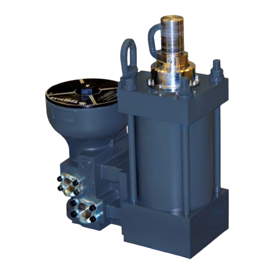
Manual 26727 VariStroke-I (VS-I) Electro-hydraulic Actuator VS-I Integrated and Remote Construction The VariStroke-I is made up of the following major components (Figure 1-1): Hydraulic Power Cylinder Rotary Servo Valve Feedback Sensors: MLDT (Magnetostrictive Linear Displacement Transducer) – for power cylinder position controlling... -
Page 16: Figure 1-2. Varistroke-I Remote, Key Features
VariStroke-I (VS-I) Electro-hydraulic Actuator Manual 26727 The VariStroke-I Remote Servo Kit (Figure 1-2) contains the same primary components as Integrated version, This kit allows the Hydraulic Power Cylinder to be mounted separately from the servo in applications where space is constrained. -
Page 17: Figure 1-3. Hydraulic Power Cylinder. Stroke Adjustment Options
Manual 26727 VariStroke-I (VS-I) Electro-hydraulic Actuator Hydraulic Power Cylinder The simple and robust design of VS-I hydraulic cylinder (Figure 1-3) is capable of consistent performance for extended periods in challenging environments. Hydraulic cylinder is designed to operate in wide range of hydraulic pressures and with high oil contamination. - Page 18 VariStroke-I (VS-I) Electro-hydraulic Actuator Manual 26727 Rotary Servo Valve The servo valve has four ports: Supply, two Control Ports, and Drain/Tank. With the hydraulic valve in its middle position, all ports are blocked. As the valve rotates, the supply is connected to a control port while simultaneously connecting the drain to the other control port.
-
Page 19: Figure 1-4. Application Example
Manual 26727 VariStroke-I (VS-I) Electro-hydraulic Actuator Figure 1-4. Application Example The shield connections for the Analog Output (terminal #20), CAN1 (terminal #23) and CAN2 (terminal #29) are through capacitors only as indicated in the wiring section of this manual. The power supply section performs the EMI filtering on the (18 to 32) V (dc) input voltage and generates controlled voltages for several electronics sub-systems. - Page 20 VariStroke-I (VS-I) Electro-hydraulic Actuator Manual 26727 Cylinder Position Control The cylinder position controller adjusts the hydraulic power cylinder position to match the feedback signal to the demand. Both the servo position controller and cylinder position controller are monitored to ensure accurate tracking.
-
Page 21: Vs-I Remote Servo Only Construction
OVBD is permanently connected to drain and can (optionally) be connected to the OVBD connection on Hydraulic Power Cylinder to drain any leakage pass the primary rod seal. Electronic Driver Module Enclosure Rotary Servo Valve with Integrated Position Sensor Figure 1-5. VariStroke-I Remote Servo, Key Features Woodward... -
Page 22: Figure 1-6. Application Example
VariStroke-I (VS-I) Electro-hydraulic Actuator Manual 26727 A unique function of the software is a periodic, symmetrically opposed impulse (called "Silt Buster") which flushes silt and debris from the servo valve without causing undue wear. At the interval and amplitude selected by the user, this function provides a very rapid motion of the hydraulic valve, allowing any silt to be flushed to the drain passage. - Page 23 Manual 26727 VariStroke-I (VS-I) Electro-hydraulic Actuator The shield connections for the Analog Output (terminal #20), CAN1 (terminal #23), and CAN2 (terminal #29) are through capacitors only as indicated in the wiring section of this manual. The power supply section performs the EMI filtering on the (18 to 32) V (dc) input voltage and generates controlled voltages for several electronics sub-systems.
-
Page 24: Figure 1-7. Nomenclature And Ordering Number Encoder
VariStroke-I (VS-I) Electro-hydraulic Actuator Manual 26727 Figure 1-7. Nomenclature and Ordering Number Encoder Woodward... -
Page 25: Chapter 2. Specifications
Manual 26727 VariStroke-I (VS-I) Electro-hydraulic Actuator Chapter 2. Specifications Physical and Performance Specifications Bore Diameter (OD) Rod Diameter (ID) 4 inches (101.6 mm) 1.75 inches (44.5 mm) 6 inches (152.4 mm) 2.5 inches (63.5 mm) 8 inches (203.2 mm) 3.5 inches (88.9 mm) 10 inches (254.0 mm) -
Page 26: Environmental Specifications
VariStroke-I (VS-I) Electro-hydraulic Actuator Manual 26727 Make sure that the VS-I hydraulic connections are installed correctly. Equipment damage is possible if the hydraulic connections are attached incorrectly (backwards). Reversed hydraulic connects will cause the actuator to operate backwards, making the fail-safe position opposite of where the user expects it to be. -
Page 27: Cylinder Position Sensor Requirements (Remote Servo Only)
It is for this reason that Woodward does NOT recommend using a combination of LVDTs and Signal Conditioners. This combination will typically result in unacceptable delays in the position sensor update rate. - Page 28 VariStroke-I (VS-I) Electro-hydraulic Actuator Manual 26727 VSI Maximum Transient Flow Rates (During Full Slew) V45 Servo V25 Servo Pressure Drop (Bar) The figure above shows the estimated hydraulic flow necessary to maintain optimum performance of the VS-I. If the flow supplied to the actuator is lower than what is specified, the actuator will continue to operate, but at reduced performance.
-
Page 29: Special Ambient Temperature Specifications / Allowances
Allowances The following information applies only to a VariStroke-I installed in a non-hazardous location. If the VariStroke-I is installed in to a Zone 1, Zone 2, Division 1, or Division 2 environment, the Special Ambient Temperature Allowances do NOT apply. -
Page 30: Stability Specifications
VariStroke-I (VS-I) Electro-hydraulic Actuator Manual 26727 Stability Specifications Before purchasing or installing a VS-I actuator, the user should verify that the actuator will be stable during operation. As shown in the relationship below, the stability of the VS-I is dependent on servo valve size, supply pressure, and the used cylinder volume. - Page 31 Manual 26727 VariStroke-I (VS-I) Electro-hydraulic Actuator Graphical representations of the stability relationship are shown in the following two charts. Woodward...
-
Page 32: Diagrams
VariStroke-I (VS-I) Electro-hydraulic Actuator Manual 26727 Diagrams Functional Block Diagram Figure 2-1. Basic Device Block Diagram without Trip Function VS-I Integrated Hydraulic Schematic Figure 2-2. VS-I Integrated Hydraulic Schematic Woodward... -
Page 33: Figure 2-3. Vs-I Remote Hydraulic Schematic
Manual 26727 VariStroke-I (VS-I) Electro-hydraulic Actuator VS-I Remote Servo Hydraulic Schematic Figure 2-3. VS-I Remote Hydraulic Schematic VS-I Servo Only Hydraulic Schematic Figure 2-4. VS-I Remote Servo Hydraulic Schematic Woodward... -
Page 34: Figure 2-5. Vs-I Spring Assist Integrated Hydraulic Schematic
VariStroke-I (VS-I) Electro-hydraulic Actuator Manual 26727 Figure 2-5. VS-I Spring Assist Integrated Hydraulic Schematic Figure 2-6. VS-I Spring Assist Remote Hydraulic Schematic Woodward... - Page 35 V25V / V45V Remote Servo Version Notes These general reference outline drawings apply to Woodward VS-I only. Consult Woodward for the latest outline drawing. Installation Orientation: Cylinder—any orientation. Servo valve—any orientation except upside down. Vertical orientation, as shown above, is recommended.
-
Page 36: Chapter 3. Installation
VariStroke-I (VS-I) Electro-hydraulic Actuator Manual 26727 Chapter 3. Installation Receiving Instructions The VS-I is carefully packed at the factory to protect it from damage during shipping; however, careless handling during shipment can result in damage. If any damage to the VS-I is discovered, immediately notify both the shipping agent and Woodward. -
Page 37: Installation Instructions
Manual 26727 VariStroke-I (VS-I) Electro-hydraulic Actuator Installation Instructions General See the outline drawings and Specifications for: Outline dimensions Hydraulic connections and fitting sizes Electrical connections Weight of the VS-I A vertical actuator position is generally preferred to conserve floor space as well as ease of making electrical and hydraulic connections. -
Page 38: Figure 3-1B. Vs-I Integrated Product Installation Interface-Bolting Pattern And Installation Features
VariStroke-I (VS-I) Electro-hydraulic Actuator Manual 26727 Figure 3-1b. VS-I Integrated Product Installation Interface—Bolting Pattern and Installation Features Woodward... -
Page 39: Figure 3-2A. Vs-I Remote. Product Installation Interface-Bolting Pattern And Installation Features
Manual 26727 VariStroke-I (VS-I) Electro-hydraulic Actuator Installation Dimensions for Remote Servo Kit Figure 3-2a. VS-I Remote. Product Installation Interface—Bolting Pattern and Installation Features Woodward... -
Page 40: Figure 3-2B. Vs-I Remote. Product Installation Interface-Bolting Pattern And Installation Features
VariStroke-I (VS-I) Electro-hydraulic Actuator Manual 26727 Figure 3-2b. VS-I Remote. Product Installation Interface—Bolting Pattern and Installation Features Table 3-1. VS-I Installation Bolts and Bolting Torques Recommendation VariStroke Bolting Min Thread Engagement Bolt Thread “T3” Cylinder Thread “T1” Min. Bolt Torque Tol. -
Page 41: Figure 3-3. Vs-I Remote Servo. Product Installation Interface-Bolting Pattern
Figure 3-3. VS-I Remote Servo. Product Installation Interface—Bolting Pattern Minimum Bolt Grade, Bolting Torque and Thread Engagement Recommendation is valid for low carbon steel mounting surface to which product is bolted. For different configuration please consult Woodward for torque and bolts grade recommendations. Woodward... -
Page 42: Figure 3-5. Vs-I Lifting Positions
VariStroke-I (VS-I) Electro-hydraulic Actuator Manual 26727 Lifting VariStroke comes equipped with lifting brackets for vertical lifting. When transporting, use both brackets as shown below. Remote Servo and Remote Cylinder have their own, separate lifting features. Both Integrated and Remote Servo units can be transported in either the vertical or horizontal position. -
Page 43: Figure 3-5. Incorrect Lifting Method
For VS-I Integrated, the user is obligated to maintain the minimum required gap between servo valve and the actuator installation surface. For reference see outline drawing (Figure 3-1). Any mounting deviation from the one recommended by Woodward might cause assembly damage, improper performance or operator injury risk. - Page 44 VariStroke-I (VS-I) Electro-hydraulic Actuator Manual 26727 Ensure that the linkages and couplings connecting the VS-I output shaft to the turbine are appropriately sized and are able to withstand the stall force and dynamic loads. The lifting eye located on the top of the VS-I Servo Valve is intended to lift ONLY the servo itself, not integrated servo-cylinder configurations.
-
Page 45: Figure 3-6. Suggested Configuration
Manual 26727 VariStroke-I (VS-I) Electro-hydraulic Actuator The hydraulic supply to the servo is to be 32 mm (1.25 inches) tubing capable of supplying 681 L/min (180 US gal/min) at 34.5 bar / 500 psig. The hydraulic drain should be 38 mm (1.5 inches) tubing or larger and must not restrict the flow of fluid from the actuator. -
Page 46: Figure 3-7. Electrical Wiring Diagram
VariStroke-I (VS-I) Electro-hydraulic Actuator Manual 26727 Electrical Connections An overall electrical wiring diagram is shown in Figure 3-8. Detailed wiring requirements for these connections will follow in the remainder of the Electrical Connections section. The RS-232 connection is covered in Chapter 4 (Installing and Running The PC Service Tool). -
Page 47: Figure 3-8. Power Supply Input Connections
Manual 26727 VariStroke-I (VS-I) Electro-hydraulic Actuator Input Power The VS-I requires a power source capable of a supplying the necessary output voltage and current at full transient conditions. The maximum power in watts (W) of a DC source can be calculated by multiplying the rated output voltage by the maximum output current capability. -
Page 48: Figure 3-9. Correct Wiring To Power Supply Input
VariStroke-I (VS-I) Electro-hydraulic Actuator Manual 26727 The VS-I is capable of connecting two redundant power supplies. The following table presents terminal assignment for this option usage. Power Input (+) Power Input (-) Power Supply #1 Terminal # 38 Terminal # 37... -
Page 49: Figure 3-11. Recommended Wiring Strain Relief
Manual 26727 VariStroke-I (VS-I) Electro-hydraulic Actuator Unit Grounding The unit housing must be grounded using the designated PE ground connection point and EMC ground connection point (see installation drawings). For the PE connection, use required type (typically green/yellow, 2.5 mm² / 12 AWG) as necessary to meet the installation safety ground requirements. -
Page 50: Figure 3-12. Analog Input Connections
50 mm (2 inches), and where possible the diameter should be maximized. Installations with severe electromagnetic interference (EMI) may require additional shielding precautions. Contact Woodward for more information. Do not ground shield on both ends, except where permitted by the control wiring diagram. -
Page 51: Figure 3-13. Final Cylinder Position Feedback Analog Input Connections
Manual 26727 VariStroke-I (VS-I) Electro-hydraulic Actuator Cylinder Position Feedback Analog Inputs (Remote Servo Only) There are two Final Cylinder Position Feedback analog inputs. Refer to the service tool chapter for information on configuring these inputs. VS-I Cylinder Position Feedback +15V... -
Page 52: Figure 3-15. Cylinder Position Sensor Wiring Diagram When Using External Power Supply
VariStroke-I (VS-I) Electro-hydraulic Actuator Manual 26727 VS-I Cylinder Position Feedback +15V Analog Inputs Feedback + Cylinder External Position Sensor Power Supply (4 – 20mA) Current limiter Feedback - DGND RIGHT Figure 3-15. Cylinder Position Sensor wiring diagram when using External Power... -
Page 53: Figure 3-19. Analog Output Connection
Manual 26727 VariStroke-I (VS-I) Electro-hydraulic Actuator Cylinder Position Feedback Analog Input Wiring Requirements: Individually shielded twisted pair cable Keep this and all other low level signal cables separated from input power cables to avoid unnecessary coupling (noise) between them. -
Page 54: Figure 3-20. Discrete Inputs Connections
VariStroke-I (VS-I) Electro-hydraulic Actuator Manual 26727 VS-I Discrete Inputs +12V_DISO Discrete Input 4 (NOT USED) DGND GND_DISO +12V_DISO Discrete Input 3 (NOT USED) DGND GND_DISO +12V_DISO Discrete Input 2 (RESET) DGND GND_DISO +12V_DISO Discrete Input 1 (RUN ENABLE IN) DGND... -
Page 55: Figure 3-21. Discrete Output Connections
/ normally closed. Refer to the service tool chapter for configuration information. The outputs can be wired to switch load from positive supply or switch load to ground. Woodward recommends that the output be used as a high side driver as shown in the diagram below. This configuration makes some common wiring faults to ground more detectable in the user system. -
Page 56: Figure 3-22. Can Ports Connections
VariStroke-I (VS-I) Electro-hydraulic Actuator Manual 26727 External Power Supply Voltage Range: 18-32 V Maximum Load Current: 500 mA Protection: The outputs are short circuit protected The outputs are recoverable after short circuit is removed Response Time: Less than 2 ms On-state Saturation Voltage: Less than 1 V @ 500 mA Off-state Leakage Current: Less than 10 μA @ 32 V... - Page 57 Manual 26727 VariStroke-I (VS-I) Electro-hydraulic Actuator CAN Specification: Interface Standard: CAN 2.0 A/B (configured in the CPU) Network Connections: (2) separate connectors Network Isolation: 500 V (ac) to chassis, input power, I/O channels, between CAN ports ...
-
Page 58: Chapter 4. Service Tool Installation
USB ports, a USB-to-serial converter is required. An approved converter can be obtained from Woodward P/N 8928-1151. Woodward offers a serial cable as a kit that can be ordered. The part number for this kit is 8928-7323, which contains a 10-foot long (3 m) DB9-F to DB9-M straight-through cable. -
Page 59: Installing The Varistroke-I Service Tool
Manual 26727 VariStroke-I (VS-I) Electro-hydraulic Actuator Installing the VariStroke-I Service Tool Use the following installation procedure to install the VariStroke-I Service Tool (Programming and Configuration Tool). Locate/obtain VS-I Service Tool Installation CD provided with each VS-I. (Alternatively, the VS-I Service Tool Installation file can be downloaded from Woodward’s website [www.woodward.com/software]). - Page 60 VariStroke-I (VS-I) Electro-hydraulic Actuator Manual 26727 The Install page appears. “Create shortcut for this program on the desktop” is set as the default. Uncheck this box if you do not want a Service Tool icon on your desktop. Click on “Install”.
-
Page 61: Connecting To The Varistroke-I
When you click on “Finish” you will exit the installation wizard. Connecting to the VariStroke-I To connect to the VariStroke-I (VS-I) connect a serial cable between the computer and the VS-I driver then double-click on the service tool icon on the desktop. - Page 62 VariStroke-I (VS-I) Electro-hydraulic Actuator Manual 26727 Press the “Connect” button in the ribbon at the top of the service tool screen. You will see the following screen. Select the network connection that the serial cable is connected to. Select your available network and then set “Baud Rate” to “AutoDetection”. Press the “Connect”...
-
Page 63: Chapter 5. Calibration And Monitoring
Manual 26727 VariStroke-I (VS-I) Electro-hydraulic Actuator Chapter 5. Calibration and Monitoring Introduction The VS-I Service Tool is organized in to a series of pages that allow the VS-I to be set up for proper operation. The following section will outline the various pages and their functions. - Page 64 VariStroke-I (VS-I) Electro-hydraulic Actuator Manual 26727 When this LED indicator is illuminated, the unit has detected Alarm LED: an operating condition, which is outside of recommended operating parameters, but the VS-I is still operating. The cause of alarm conditions should be determined and corrected to prevent damage to the turbine, VS-I, or other auxiliary equipment.
-
Page 65: System Information Page
Manual 26727 VariStroke-I (VS-I) Electro-hydraulic Actuator System Information Page This page will display system information about the VS-I servo that is currently connected to the PC Service Tool. Figure 5-1. System Information Page Actuator P/N, S/N, Revision: These fields display the Actuator Assembly Part Number (P/N), Serial Number (S/N), and Revision Number. -
Page 66: Configuration And Calibration
VariStroke-I (VS-I) Electro-hydraulic Actuator Manual 26727 Configuration and Calibration To prevent personal injury or death and damage to equipment, the controlled prime mover must not be allowed to run or operate during any of the following procedures. The main steam valve or main fuel control must be turned off to prevent operation of the controlled system. - Page 67 (4–20 mA) range. For a list of standard / Woodward position sensor lengths used in Integrated and Remote Servo Kits, refer to the table shown in Chapter 7: Repair and Troubleshooting.
-
Page 68: Cylinder Configuration
VariStroke-I (VS-I) Electro-hydraulic Actuator Manual 26727 Cylinder Configuration Before starting the configuration, the unit must be in a safe and shut-down state. The unit can be shut down by putting 0 mA onto the analog inputs or by opening the “run enable” discrete input (note: the “run enable” must be set to “used”). The unit must also not have any active faults, such as a Cylinder Tracking Fault. - Page 69 Manual 26727 VariStroke-I (VS-I) Electro-hydraulic Actuator Soft seating: The VS-I Soft Seating function allows the actuator to a have different Slew Rate limits when positioned within the lower 10% of the total calibrated stroke. This feature provides a behavior similar to that of a conventional hydraulic cushion.
- Page 70 VariStroke-I (VS-I) Electro-hydraulic Actuator Manual 26727 Find Minimum Stop ALL SHUTDOWNS must be cleared in order to proceed with calibration. These can be seen on the “Alarms/Shutdowns” page of the PC Service Tool. It may be necessary to temporarily disable certain shut downs to complete the calibration.
- Page 71 Manual 26727 VariStroke-I (VS-I) Electro-hydraulic Actuator To use the Find Minimum Stop option, press the “Find Minimum Stop” button. The Find Minimum Stop feature allows the user to scale the desired minimum position offset and maximum stop position to the 4 to 20 mA demand input range.
- Page 72 VariStroke-I (VS-I) Electro-hydraulic Actuator Manual 26727 Find Minimum AND Maximum Stops ALL SHUTDOWNS must be cleared in order to proceed with calibration. These can be seen on the “Alarms/Shutdowns” page of the PC Service Tool. It may be necessary to temporarily disable certain shut downs to complete the calibration.
- Page 73 Manual 26727 VariStroke-I (VS-I) Electro-hydraulic Actuator Set Offset and Maximum Stop Position If one of the calibration routines has already been run, or the user wishes to adjust these values based on the factory calibration, the “Adjust Minimum Offset and Maximum Position” button may be pressed.
-
Page 74: Manual Operation
VariStroke-I (VS-I) Electro-hydraulic Actuator Manual 26727 Manual Operation To prevent personal injury or death and damage to equipment, the controlled prime mover must not be allowed to run or operate during any of the following procedures. The main steam valve or main fuel control must be turned off to prevent operation of the controlled system. -
Page 75: Chapter 6. Configuration
Manual 26727 VariStroke-I (VS-I) Electro-hydraulic Actuator Chapter 6. Configuration Input Configuration The analog input settings including scaling and diagnostics levels are displayed from this screen. The values of the current operational and diagnostic settings are also displayed. Analog Demand Inputs 1&2 Current Reading: Displays the current value of the analog input signal in mA and percent of full stroke for the analog input channels 1 and 2. - Page 76 VariStroke-I (VS-I) Electro-hydraulic Actuator Manual 26727 Demand Inputs Demand Input 1 / 2: Displays the value (in percent position) of the individual demand signals. Demand: Displays the value (in percent position) of the demand signals after they have been averaged, low signal selected, or high signal selected.
-
Page 77: Output Configuration
Manual 26727 VariStroke-I (VS-I) Electro-hydraulic Actuator Run Enable If the Run Enable is toggled to USED while the circuit is open, the actuator will immediately shut down. Run Enable: This input either enables or disables the Run Enable functionality. If Used is selected, and the Run Enable circuit is opened, then the system will ignore the analog demand input signals and shut down. - Page 78 VariStroke-I (VS-I) Electro-hydraulic Actuator Manual 26727 Alarm / Shutdown Discrete Outputs Alarm / Shutdown Indication: Any flag marked as an alarm will cause the discrete output relay to energize. Alarm / Shutdown Results In: Sets the state at which the discrete output relay will be when energized.
-
Page 79: Advanced Configuration
Manual 26727 VariStroke-I (VS-I) Electro-hydraulic Actuator Input Demand: The Analog Output will equal the Demand Input. Actual Position: The Analog Output will equal the Feedback Position based on the configurable Analog Output Scaling. Current Reading: Analog Output reading in mA. -
Page 80: Linearization
VariStroke-I (VS-I) Electro-hydraulic Actuator Manual 26727 Linearization This table is used to linearize steam flow to actuator position. It can only be modified when the actuator is shut down. Enabled / Disabled: Enables or Disables the demand curve (linearization) functionality. - Page 81 Manual 26727 VariStroke-I (VS-I) Electro-hydraulic Actuator Diagnostic Values: Supply Voltage: Indicates the supply voltage value. Internal Actuator Drive Current: Indicates the actuator drive current. Configure Alarms/Shutdowns Page From the Alarm/Shutdown Configuration page, some of the alarms and shut downs can be configured. Faults that can be edited are shown as colored buttons on the page.
-
Page 82: Saving And Loading Settings
VariStroke-I (VS-I) Electro-hydraulic Actuator Manual 26727 Changing these settings may cause the actuator to move and/or shut down. Ensure all personnel are clear of moving components before changing values. If an active Alarm is toggled to a Shut down, the actuator will immediately shut down. -
Page 83: Chapter 7. Repair And Troubleshooting
General The Varistroke-I is warranted to be free from defects in materials and workmanship, when installed and used in the manner for which it was intended, for a period of 36 months from the date of shipment from Woodward. -
Page 84: Troubleshooting
VariStroke-I (VS-I) Electro-hydraulic Actuator Manual 26727 Troubleshooting General The following troubleshooting guide will help you isolate trouble with the servo valve, hydraulic power cylinder, control circuit board, wiring, and system problems. Troubleshooting beyond this level is recommended ONLY when complete facility control testing is available. - Page 85 Manual 26727 VariStroke-I (VS-I) Electro-hydraulic Actuator Table 7-1. VS-I General Troubleshooting Guide General Faults Problem Cause Remedy It is normal for this to occur when a shut down position has been commanded from an external source. I.E. Service Tool, Digital Take away command and reset VS-I Communication or Discrete Input.
- Page 86 VariStroke-I (VS-I) Electro-hydraulic Actuator Manual 26727 Table 7-2. VS-I Demand Faults Guide Demand Faults Problem / Alarm Cause Remedy Ensure the Used / Not Used settings inside the VS-I match the Active/Inactive settings of the Run Enable circuit is open, or Run controller.
- Page 87 Manual 26727 VariStroke-I (VS-I) Electro-hydraulic Actuator Table 7-3. VS-I Power Supply Faults Power Supply Faults Problem Cause Remedy It is normal for the Power Up Reset diagnostic to occur upon Issue a reset to the VS-I. power up of the VS-I.
- Page 88 VariStroke-I (VS-I) Electro-hydraulic Actuator Manual 26727 Table 7-4. VS-I Feedback Faults Feedback Faults Problem Cause Remedy Position 1 / 2 Feedback Low Detection: Check all connections to the final Power cylinder feedback 1 < 4 mA cylinder; check for any impediment...
- Page 89 Manual 26727 VariStroke-I (VS-I) Electro-hydraulic Actuator Table 7-5. VS-I Temperature Faults Temperature Faults Problem Cause Remedy Current limits reduced because of high temperature. Limits will Temperature Derating Active automatically reset. Reduce ambient temperature to The ambient temperature of the within specification limits.
- Page 90 VariStroke-I (VS-I) Electro-hydraulic Actuator Manual 26727 Table 7-6. Performance Faults Performance Faults Problem Cause Remedy Broken return spring Spring Check Failed Detection: Service is required. Start up test showed a detected failure Servo valve seizure of the servo valve safety return spring.
-
Page 91: Maintenance
Manual 26727 VariStroke-I (VS-I) Electro-hydraulic Actuator Table 7-6. Performance Faults (continued) Performance Faults Problem Cause Remedy Incorrect configuration and Stability Warning calibration settings. Detection: See Chapter 2: Stability The settings for Supply Pressure, Specifications for the details of this Offset at Minimum Position, and The VS-I servo valve is too large alarm. -
Page 92: Chapter 8. Product Support And Service Options
A Recognized Turbine Retrofitter (RTR) is an independent company that does both steam and gas turbine control retrofits and upgrades globally, and can provide the full line of Woodward systems and components for the retrofits and overhauls, long term service contracts, emergency repairs, etc. -
Page 93: Returning Equipment For Repair
Flat Rate Remanufacture: Flat Rate Remanufacture is very similar to the Flat Rate Repair option with the exception that the unit will be returned to you in “like- new” condition and carry with it the full standard Woodward product warranty (Woodward Product and Service Warranty 5-01-1205). This option is applicable to mechanical products only. -
Page 94: Replacement Parts
Engineering Services Woodward offers various Engineering Services for our products. For these services, you can contact us by telephone, by email, or through the Woodward website. Technical Support ... -
Page 95: Technical Assistance
VariStroke-I (VS-I) Electro-hydraulic Actuator Technical Assistance If you need to contact technical assistance, you will need to provide the following information. Please write it down here before contacting the Engine OEM, the Packager, a Woodward Business Partner, or the Woodward factory: General... -
Page 96: Chapter 9. Asset Management And Refurbishment Scheduling Period
Contact your local Woodward representative for a detailed evaluation of your site conditions to determine the right maintenance cycles for your installation. Woodward’s overhaul services will return the unit to “like new” condition ready for another full operating cycle, lasting until the next planned maintenance outage. - Page 97 Manual 26727 VariStroke-I (VS-I) Electro-hydraulic Actuator Appendices Outline Drawings and Installation Features Woodward...
-
Page 98: Appendix A - V25 Servo, 4-Inch (100Mm) Bore Integrated Servo-Cylinder (V25Td-10Xx)
VariStroke-I (VS-I) Electro-hydraulic Actuator Manual 26727 Appendix A – V25 Servo, 4-inch (100mm) Bore Integrated Servo-Cylinder (V25TD-10XX) Figure A-1a. V25TD-10XX Integrated Installation Dimensions Woodward... -
Page 99: Figure A-1B. V25Td-10Xx Integrated Installation Dimensions
Manual 26727 VariStroke-I (VS-I) Electro-hydraulic Actuator Figure A-1b. V25TD-10XX Integrated Installation Dimensions Woodward... -
Page 100: Appendix B - V25 Servo, 6-Inch (150Mm) Bore Integrated Servo-Cylinder (V25Td-15Xx)
VariStroke-I (VS-I) Electro-hydraulic Actuator Manual 26727 Appendix B – V25 Servo, 6-inch (150mm) Bore Integrated Servo-Cylinder (V25TD-15XX) Figure B-1a. V25TD-15XX Integrated Installation Dimensions Woodward... -
Page 101: Figure A-2B. V25Td-15Xx Integrated Installation Dimensions
Manual 26727 VariStroke-I (VS-I) Electro-hydraulic Actuator Figure B-1b. V25TD-15XX Integrated Installation Dimensions Woodward... -
Page 102: Appendix C - V45 Servo, 6-Inch (150Mm) Bore Integrated Servo-Cylinder (V45Td-15Xx)
VariStroke-I (VS-I) Electro-hydraulic Actuator Manual 26727 Appendix C – V45 Servo, 6-inch (150mm) Bore Integrated Servo-Cylinder (V45TD-15XX) Figure C-1a. V45TD-15XX Integrated Installation Dimensions Woodward... -
Page 103: Figure A-3B. V45Td-15Xx Integrated Installation Dimensions
Manual 26727 VariStroke-I (VS-I) Electro-hydraulic Actuator Figure C-2b. V45TD-15XX Integrated Installation Dimensions Woodward... -
Page 104: Appendix D - V45 Servo, 8-Inch (200Mm) Bore Integrated Servo-Cylinder (V45Td-20Xx)
VariStroke-I (VS-I) Electro-hydraulic Actuator Manual 26727 Appendix D – V45 Servo, 8-inch (200mm) Bore Integrated Servo-Cylinder (V45TD-20XX) Figure D-1a. V45TD-20XX Integrated Installation Dimensions Woodward... -
Page 105: Figure A-4B. V45Td-20Xx Integrated Installation Dimensions
Manual 26727 VariStroke-I (VS-I) Electro-hydraulic Actuator Figure D-1b. V45TD-20XX Integrated Installation Dimensions Woodward... -
Page 106: Appendix E - V45 Servo, 10-Inch (250Mm) Bore Integrated Servo-Cylinder (V45Td-25Xx)
VariStroke-I (VS-I) Electro-hydraulic Actuator Manual 26727 Appendix E – V45 Servo, 10-inch (250mm) Bore Integrated Servo-Cylinder (V45TD-25XX) Figure E-1a. V45TD-25XX Integrated Installation Dimensions Woodward... - Page 107 Manual 26727 VariStroke-I (VS-I) Electro-hydraulic Actuator Figure E-1b. V45TD-25XX Integrated Installation Dimensions Woodward...
-
Page 108: Appendix F - V45 Servo, 8-Inch (200Mm) Bore 3-Inch (75Mm) Stroke Integrated Spring Assist Servo-Cylinder (V45Tt-2007-Mue)
VariStroke-I (VS-I) Electro-hydraulic Actuator Manual 26727 Appendix F – V45 Servo, 8-inch (200mm) Bore 3-inch (75mm) Stroke Integrated Spring Assist Servo- Cylinder (V45TT-2007-MUE) Figure F-1a. V45TT-2007-MUE Integrated Spring Assist Installation Dimensions Woodward... - Page 109 Manual 26727 VariStroke-I (VS-I) Electro-hydraulic Actuator Figure F-1b. V45TT-2007-MUE Integrated Spring Assist Installation Dimensions Woodward...
-
Page 110: Appendix G - V25 Servo, 4-Inch (100Mm) Bore Remote Servo-Cylinder (V25Rd-10Xx)
VariStroke-I (VS-I) Electro-hydraulic Actuator Manual 26727 Appendix G – V25 Servo, 4-inch (100mm) Bore Remote Servo-Cylinder (V25RD-10XX) Figure G-1a. VS-I Remote Maximum Allowable Distance between Actuator and Servo Woodward... - Page 111 Manual 26727 VariStroke-I (VS-I) Electro-hydraulic Actuator Figure G-1b. V25RD-10XX Remote Installation Dimensions Woodward...
- Page 112 VariStroke-I (VS-I) Electro-hydraulic Actuator Manual 26727 Figure G-1c. V25RD-10XX Remote Installation Dimensions Woodward...
-
Page 113: Appendix H - V25 Servo, 6-Inch (150Mm) Bore Remote Servo-Cylinder (V25Rd-15Xx)
Manual 26727 VariStroke-I (VS-I) Electro-hydraulic Actuator Appendix H – V25 Servo, 6-inch (150mm) Bore Remote Servo-Cylinder (V25RD-15XX) Figure H-1a. VS-I Remote Maximum Allowable Distance between Actuator and Servo Woodward... - Page 114 VariStroke-I (VS-I) Electro-hydraulic Actuator Manual 26727 Figure H-1b. V25RD-15XX Remote Installation Dimensions Woodward...
- Page 115 Manual 26727 VariStroke-I (VS-I) Electro-hydraulic Actuator Figure H-1c. V25RD-15XX Remote Installation Dimensions Woodward...
-
Page 116: Appendix I - V45 Servo, 6-Inch (150Mm) Bore Remote Servo-Cylinder (V45Rd-15Xx)
VariStroke-I (VS-I) Electro-hydraulic Actuator Manual 26727 Appendix I – V45 Servo, 6-inch (150mm) Bore Remote Servo-Cylinder (V45RD-15XX) Figure I-1a. VS-I Remote Maximum Allowable Distance between Actuator and Servo Woodward... - Page 117 Manual 26727 VariStroke-I (VS-I) Electro-hydraulic Actuator Figure I-1b. V45RD-15XX Remote Installation Dimensions Woodward...
- Page 118 VariStroke-I (VS-I) Electro-hydraulic Actuator Manual 26727 Figure I-1c. V45RD-15XX Remote Installation Dimensions Woodward...
-
Page 119: Appendix J - V45 Servo, 8-Inch (200Mm) Bore Remote Servo-Cylinder (V45Rd-20Xx)
Manual 26727 VariStroke-I (VS-I) Electro-hydraulic Actuator Appendix J – V45 Servo, 8-inch (200mm) Bore Remote Servo-Cylinder (V45RD-20XX) Figure J-1a. VS-I Remote Maximum Allowable Distance between Actuator and Servo Woodward... - Page 120 VariStroke-I (VS-I) Electro-hydraulic Actuator Manual 26727 Figure J-1b. V45RD-20XX Remote Installation Dimensions Woodward...
- Page 121 Manual 26727 VariStroke-I (VS-I) Electro-hydraulic Actuator Figure J-1c. V45RD-20XX Remote Installation Dimensions Woodward...
-
Page 122: Appendix K - V45 Servo, 10-Inch (250Mm) Bore Remote Servo-Cylinder (V45Rd-25Xx)
VariStroke-I (VS-I) Electro-hydraulic Actuator Manual 26727 Appendix K – V45 Servo, 10-inch (250mm) Bore Remote Servo-Cylinder (V45RD-25XX) Figure K-1a. VS-I Remote Maximum Allowable Distance between Actuator and Servo Woodward... - Page 123 Manual 26727 VariStroke-I (VS-I) Electro-hydraulic Actuator Figure K-1b. V45RD-25XX Remote Installation Dimensions Woodward...
- Page 124 VariStroke-I (VS-I) Electro-hydraulic Actuator Manual 26727 Figure K-1c. V45RD-25XX Remote Installation Dimensions Woodward...
-
Page 125: Appendix L - V45 Servo, 8-Inch (200Mm) Bore 3-Inch (75Mm) Stroke Remote Spring Assist Servo-Cylinder (V45Rt-2007-Mue)
Manual 26727 VariStroke-I (VS-I) Electro-hydraulic Actuator Appendix L – V45 Servo, 8-inch (200mm) Bore 3-inch (75mm) Stroke Remote Spring Assist Servo-Cylinder (V45RT-2007-MUE) Figure L-1a. VS-I Remote Maximum Allowable Distance between Actuator and Servo Woodward... - Page 126 VariStroke-I (VS-I) Electro-hydraulic Actuator Manual 26727 Figure L-1b. V45RT-2007-MUE Remote Spring Assis Installation Dimensions Woodward...
- Page 127 Manual 26727 VariStroke-I (VS-I) Electro-hydraulic Actuator Figure L-1c. V45RT-2007-MUE Remote Spring Assis Installation Dimensions Woodward...
-
Page 128: Appendix M - Remote Servo Version
VariStroke-I (VS-I) Electro-hydraulic Actuator Manual 26727 Appendix M – Remote Servo Version Figure M-1a. Typical VS-I Remote Servo Installation Dimensions Woodward... - Page 129 Manual 26727 VariStroke-I (VS-I) Electro-hydraulic Actuator Figure M-1b. Typical VS-I Remote Servo Installation Dimensions Woodward...
-
Page 130: Revision History
VariStroke-I (VS-I) Electro-hydraulic Actuator Manual 26727 Revision History Changes in Revision F— Miscellaneous updates as marked with change bars Appendices A through M and associated figures Changes in Revision E— Miscellaneous updates as marked with change bars Changes in Revision D—... -
Page 131: Declarations
Manual 26727 VariStroke-I (VS-I) Electro-hydraulic Actuator Declarations Woodward... - Page 132 VariStroke-I (VS-I) Electro-hydraulic Actuator Manual 26727 Woodward...
- Page 133 Email and Website—www.woodward.com Woodward has company-owned plants, subsidiaries, and branches, as well as authorized distributors and other authorized service and sales facilities throughout the world. Complete address / phone / fax / email information for all locations is available on our website.
Need help?
Do you have a question about the VariStroke-I and is the answer not in the manual?
Questions and answers