Sign In
Upload
Download
Table of Contents
Contents
Add to my manuals
Delete from my manuals
Share
URL of this page:
HTML Link:
Bookmark this page
Add
Manual will be automatically added to "My Manuals"
Print this page
×
Bookmark added
×
Added to my manuals
Manuals
Brands
RUPTELA Manuals
GPS
PRO3
User manual
RUPTELA PRO3 User Manual
For more information, please visit
ruptela.com
Hide thumbs
1
Table Of Contents
2
3
4
5
6
7
8
9
10
11
12
13
14
15
16
17
18
19
20
21
22
23
24
25
26
27
28
29
30
31
32
33
34
35
36
37
38
39
40
41
42
43
44
45
46
47
48
49
50
51
52
53
54
55
56
57
58
59
60
61
62
63
64
65
66
67
page
of
67
Go
/
67
Contents
Table of Contents
Bookmarks
Table of Contents
Table of Contents
1 Introduction
Acronyms and Terms Used in Document
Legal Notice
Safety Requirements
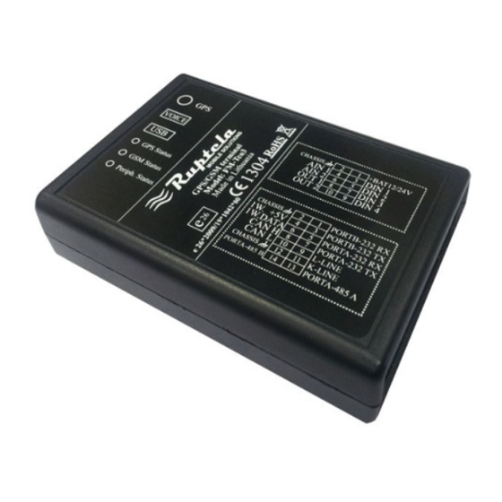
2 Fm-Pro3
Basic Description
Package Contents
Additional Accessories
Basic Characteristics
Technical Features
Fm-Pro3 Dimensions
Led Statuses
Pinout Connection, Usb
Special Features
Qualification and Certification
3 Fm-Eco3
Basic Description
Package Contents
Additional Accessories
Basic Characteristics
Technical Features
Fm-Eco3 Dimensions
Led Statuses
Pinout Connection, Usb
Special Features
Qualification and Certification
4 Fm-Tco3
Basic Description
Package Contents
Additional Accessories
Basic Characteristics
Technical Features
Fm-Tco3 Dimensions
Led Statuses
Pinout Connection, Usb
Special Features
Qualification and Certification
5 Installation and Configuration Instructions
Module Installation
Device Connection to a Personal Computer
System Requirements
Preparation for Connection
Driver Installation
Configurator
Interfacing to Com Port
Global Parameter Configuration
Profile Configuration
Saving and Loading Configuration
Configuration Exchange with a Device
Firmware Update
Appendix - Io List
Advertisement
Quick Links
1
Configurator
Download this manual
User Manual
FM
ECO3 / PRO3 / TCO3 /
Version 7. Last update 2013-08-27
© All rights reserved to
Ruptela UAB
Table of
Contents
Previous
Page
Next
Page
1
2
3
4
5
Advertisement
Table of Contents
Need help?
Do you have a question about the PRO3 and is the answer not in the manual?
Ask a question
Questions and answers
Related Manuals for RUPTELA PRO3
GPS RUPTELA Pro5 User Manual
(50 pages)
GPS RUPTELA FM-Pro3 Manual Manual
Gps/ gsm terminal (18 pages)
GPS RUPTELA FM-Eco3 Configuration Manual
(22 pages)
GPS RUPTELA ECO3 User Manual
(67 pages)
GPS RUPTELA FM-Pro4 User Manual
(37 pages)
GPS RUPTELA fm-eco4 light 3g User Manual
(30 pages)
GPS Ruptela FM-Plug4 User Manual
(29 pages)
GPS Ruptela FM-Eco4 User Manual
(33 pages)
GPS Ruptela FM-Eco4 User Manual
(31 pages)
GPS RUPTELA FM-Tco4 HCV User Manual
(44 pages)
GPS RUPTELA FM-Eco4 light User Manual
(33 pages)
GPS RUPTELA FM-Plug 4 User Manual
(34 pages)
GPS RUPTELA FM-Eco4S Series User Manual
(41 pages)
GPS RUPTELA FM-Eco4 S Series User Manual
(49 pages)
GPS RUPTELA FM-Pro4 User Manual
(42 pages)
GPS RUPTELA FM Pro Sms Commands List
(41 pages)
This manual is also suitable for:
Eco3
Tco3
Table of Contents
Print
Rename the bookmark
Delete bookmark?
Delete from my manuals?
Login
Sign In
OR
Sign in with Facebook
Sign in with Google
Upload manual
Upload from disk
Upload from URL


Need help?
Do you have a question about the PRO3 and is the answer not in the manual?
Questions and answers