
Related Manuals for Allen-Bradley POINT I/O 1734-IB4D


Summary of Contents for Allen-Bradley POINT I/O 1734-IB4D
-
Page 1: Table Of Contents
Installation Instructions POINT I/O 24V DC 4-channel Discrete Input Module with Diagnostics Catalog Number 1734-IB4D Table of Contents Topic Page Important User Information Environment and Enclosure Prevent Electrostatic Discharge About the Module Before You Begin Understand Short Circuit Detection Understand Open-wire Detection Install the Mounting Base Install the Module Install the Removable Terminal Block... -
Page 2: Important User Information
2 POINT I/O 24V DC 4-channel Discrete Input Module with Diagnostics Important User Information Solid state equipment has operational characteristics differing from those of electromechanical equipment. Safety Guidelines for the Application, Installation and Maintenance of Solid State Controls (Publication SGI-1.1 available from your local Rockwell Automation sales office or online at http://literature.rockwellautomation.com) describes some important differences between solid state equipment and hard-wired electromechanical devices. -
Page 3: Environment And Enclosure
POINT I/O 24V DC 4-channel Discrete Input Module with Diagnostics Environment and Enclosure ATTENTION: This equipment is intended for use in a Pollution Degree 2 industrial environment, in overvoltage Category II applications (as defined in EN/IEC 60664-1), at altitudes up to 2000 m (6562 ft) without derating. This equipment is not intended for use in residential environments and may not provide adequate protection to radio communication services in such environments. -
Page 4: Prevent Electrostatic Discharge
4 POINT I/O 24V DC 4-channel Discrete Input Module with Diagnostics Prevent Electrostatic Discharge ATTENTION: This equipment is sensitive to electrostatic discharge, which can cause internal damage and affect normal operation. Follow these guidelines when you handle this equipment: • Touch a grounded object to discharge potential static. •... - Page 5 POINT I/O 24V DC 4-channel Discrete Input Module with Diagnostics Electrical Safety Considerations ATTENTION: This equipment is certified for use only within the surrounding air temperature range of 0…55 °C (32…131 °F). The equipment must not be used outside of this range. At the end of its life, this equipment should be collected separately from any unsorted municipal waste.
-
Page 6: About The Module
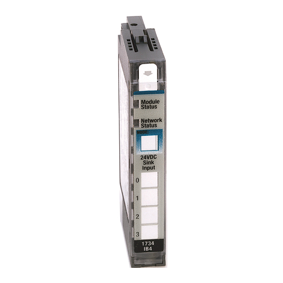
6 POINT I/O 24V DC 4-channel Discrete Input Module with Diagnostics About the Module This module is a 4-channel 24V DC input module with short circuit and open-wire diagnostics. See the figures to familiarize yourself with major parts of the module, noting that the wiring base assembly is one of the following, with the module not being compatible with 1734-TB3, 1734-TB3S, 1734-TOP3, and 1734-TOP3S bases: •... -
Page 7: Before You Begin
POINT I/O 24V DC 4-channel Discrete Input Module with Diagnostics POINT I/O Input Module with 1734-TOP or 1734-TOPS Base Slide-in writable label Module locking mechanism Insertable Module wiring diagram I/O module DIN Rail locking screw (orange) Handle Mechanical One-piece Keying (orange) terminal base with screw or... -
Page 8: Understand Open-Wire Detection
8 POINT I/O 24V DC 4-channel Discrete Input Module with Diagnostics When the SSV is loaded to the maximum rated current of 50 mA, a voltage drop of as much as 2.5V DC can exist between the user auxiliary power and the SSV connection. For example, for a supply of 10V DC to a sensor with power derived from the SSV, a supply of 12.5V DC is needed at the auxiliary power connection. -
Page 9: Install The Mounting Base
POINT I/O 24V DC 4-channel Discrete Input Module with Diagnostics Install the Mounting Base To install the mounting base on the DIN rail, proceed as follows: 1. Position the mounting base vertically above the installed units, for example, adapter, power supply, or existing module. 2. -
Page 10: Install The Module
10 POINT I/O 24V DC 4-channel Discrete Input Module with Diagnostics Install the Module Install the module before or after base installation. Before installing the module into the mounting base be sure of this. • The mounting base is correctly keyed. •... - Page 11 POINT I/O 24V DC 4-channel Discrete Input Module with Diagnostics 1734-TOP Base Be sure that the DIN rail locking screw is in the horizontal position. Turn the keyswitch to align the number with the notch. Notch position 1 is shown. 44228 To install the module, use this procedure: 1.
- Page 12 12 POINT I/O 24V DC 4-channel Discrete Input Module with Diagnostics 4. Insert the end opposite the handle into the base unit, noting this end has a curved section that engages with the wiring base. 5. Rotate the terminal block into the wiring base until it locks itself in place. 6.
-
Page 13: Install The Removable Terminal Block
POINT I/O 24V DC 4-channel Discrete Input Module with Diagnostics Install the Removable Terminal Block Read this for information if a removable terminal block (RTB) is supplied with your wiring base assembly, noting that 1734-TOP and 1734-TOPS bases do not have an RTB. To insert the RTB, proceed as follows. -
Page 14: Wire The Module
14 POINT I/O 24V DC 4-channel Discrete Input Module with Diagnostics Wire the Module See the figure and tables for information about how to wire the module. 1734-IB4D Module status Network status Status of input 0 Status of input 1 Status of input 2 Status of input 3 Input 0... - Page 15 POINT I/O 24V DC 4-channel Discrete Input Module with Diagnostics Wiring Sink Input Prox In 0 Prox In 1 Prox In 2 Prox In 3 44226 V=10/28.8V DC If a common connection is required (three-wire devices), then a 1734-CTM common terminal module can be required. POINT I/O Input Module Channel Terminal Number...
-
Page 16: Configure The Module
16 POINT I/O 24V DC 4-channel Discrete Input Module with Diagnostics Configure the Module Read this section for information about how to communicate with your module. I/O messages are sent to (consumed) and received from (produced) the POINT I/O modules. These messages are mapped into the memory of the processor or scanner. This POINT I/O input module produces 1 byte or 2 bytes of input data based on which produced assembly is selected. - Page 17 POINT I/O 24V DC 4-channel Discrete Input Module with Diagnostics Default Data Map – Configuration Assembly Instance 103 Message Size: 18 Bytes Consume 4 Input 1 off to on filter byte 0 Consume 5 Input 1 off to on filter byte 1 Consume 6 Input 1 on to off filter byte 0 Consume 7...
-
Page 18: Interpret The Indicators
18 POINT I/O 24V DC 4-channel Discrete Input Module with Diagnostics Interpret the Indicators See the figure and table that show how to interpret LED indicators. 1734-IB4D Module status Network status Status of input 0 Status of input 1 Status of input 2 Status of input 3 44217 Interpret LED Indicators Module Status... - Page 19 POINT I/O 24V DC 4-channel Discrete Input Module with Diagnostics Interpret LED Indicators Network Status Indication Probable Cause Recommended Action Network Status Device is not online. Apply power to device, wait for – Device has not completed dup_MAC_id to complete, and correct, dup_MAC_id test.
-
Page 20: Remove A Mounting Base
20 POINT I/O 24V DC 4-channel Discrete Input Module with Diagnostics Remove a Mounting Base To remove a mounting base, you must first remove any installed module and the module that is installed in the base to the right. 1. For a module with a two-piece terminal base, use these steps; otherwise, use step −... -
Page 21: Specifications
POINT I/O 24V DC 4-channel Discrete Input Module with Diagnostics Specifications POINT I/O 24V DC 4-channel Digital Diagnostics Input Module – 1734-IB4D Attribute Value Module location 1734-TB, 1734-TBS, 1734-TOP, and 1734-TOPS bases POINTBus current, max 50 mA @ 5V DC Power dissipation, max 0.6 W @ 28.8V DC Thermal dissipation, max... - Page 22 22 POINT I/O 24V DC 4-channel Discrete Input Module with Diagnostics Environmental Specifications Attribute Value Temperature, operating IEC 60068-2-1 (Test Ad, operating cold), IEC 60068-2-2 (Test Bd, operating dry heat), IEC 60068-2-14 (Test Nb, operating thermal shock): 0 °C < Ta < 55 °C (32 °F < Ta < 131 °F) Temperature, nonoperating IEC 60068-2-1 (Test Ab, unpackaged nonoperating cold), IEC 60068-2-2 (Test Bb, unpackaged nonoperating dry heat),...
- Page 23 POINT I/O 24V DC 4-channel Discrete Input Module with Diagnostics Certifications Certification (When Value Product Is Marked) European Union 2014/30/EU EMC Directive, compliant with: EN 61000-6-4; Industrial Emissions EN 61131-2; Programmable Controllers (Clause 8, Zone A & B) EN 61326-1; Measurement/Control/Laboratory use, Industrial requirements European Union 2011/65/EU RoHS, compliant with: EN 50581;...
- Page 24 Rockwell Automation maintains current product environmental information on its website at http://www.rockwellautomation.com/rockwellautomation/about-us/sustainability-ethics/product-environmental-compliance.page. Allen-Bradley, Rockwell Automation, POINT I/O, RSLogix 5000, and TechConnect are trademarks of Rockwell Automation, Inc. Trademarks not belonging to Rockwell Automation are property of their respective companies. Publication 1734-IN029B-EN-E - July 2018 Supersedes Publication 1734-IN029A-EN-E - January 2007 Copyright ©...
Need help?
Do you have a question about the POINT I/O 1734-IB4D and is the answer not in the manual?
Questions and answers