Allen-Bradley 1734-OE2C Installation Instructions Manual
Series c,
point i/o 2 current output and
2 voltage output analog modules
Hide thumbs
Also See for 1734-OE2C:
- User manual (221 pages) ,
- Installation instructions manual (12 pages)
Table of Contents
Advertisement
Installation Instructions
POINT I/O 2 Current Output and
2 Voltage Output Analog Modules
Catalog Numbers 1734-OE2C, 1734-OE2V, Series C
Table of Contents
Topic
Important User Information
Environment and Enclosure
Preventing Electrostatic Discharge
North American Hazardous Location Approval
European Hazardous Location Approval
Before You Begin
Identify Module Components
Install the Mounting Base
Install the Module
Install the Removable Terminal Block (RTB)
Remove a Mounting Base
Communicate with Your Module
Wire the Module
Troubleshoot with Indicators
Placing Series C Analog Current Output Modules
Specifications
Page
2
3
3
4
5
6
6
7
8
9
11
12
13
16
18
18
Advertisement
Table of Contents

Related Manuals for Allen-Bradley 1734-OE2C


Summary of Contents for Allen-Bradley 1734-OE2C
- Page 1 Installation Instructions POINT I/O 2 Current Output and 2 Voltage Output Analog Modules Catalog Numbers 1734-OE2C, 1734-OE2V, Series C Table of Contents Topic Page Important User Information Environment and Enclosure Preventing Electrostatic Discharge North American Hazardous Location Approval European Hazardous Location Approval...
-
Page 2: Important User Information
2 POINT I/O 2 Current Output and 2 Voltage Output Analog Modules Important User Information Solid-state equipment has operational characteristics differing from those of electromechanical equipment. Safety Guidelines for the Application, Installation and Maintenance of Solid State Controls (Publication SGI-1.1 available from your local Rockwell Automation sales office or online at http://www.rockwellautomation.com/literature/) describes some important differences between solid-state equipment and hard-wired electromechanical devices. -
Page 3: Environment And Enclosure
POINT I/O 2 Current Output and 2 Voltage Output Analog Modules Environment and Enclosure ATTENTION: This equipment is intended for use in a Pollution Degree 2 industrial environment, in overvoltage Category II applications (as defined in IEC publication 60664-1), at altitudes up to 2000 meters without derating. This equipment is not intended for use in residential environments and may not provide adequate protection to radio communication services in such environments. -
Page 4: North American Hazardous Location Approval
4 POINT I/O 2 Current Output and 2 Voltage Output Analog Modules North American Hazardous Location Approval The following information applies when Informations sur l'utilisation de cet équipement operating this equipment in hazardous en environnements dangereux: locations: Products marked "CL I, DIV 2, GP A, B, C, D" are suitable Les produits marqués "CL I, DIV 2, GP A, B, C, D"... -
Page 5: European Hazardous Location Approval
POINT I/O 2 Current Output and 2 Voltage Output Analog Modules European Hazardous Location Approval The following applies when the product bears the Ex Marking This equipment is intended for use in potentially explosive atmospheres as defined by European Union Directive 2014/34/EU. DEMKO certifies that this equipment has been found to comply with the Essential Health and Safety Requirements relating to the design and construction of Category 3 equipment intended for use in Zone 2 potentially explosive atmospheres, given in Annex II to this... -
Page 6: Before You Begin
6 POINT I/O 2 Current Output and 2 Voltage Output Analog Modules Before You Begin You can use these Series C modules with DeviceNet and PROFIBUS adapters. If you are using RSLogix 5000 software, version 11 or higher, you can also use the Series C modules with ControlNet and Ethernet adapters. -
Page 7: Install The Mounting Base
45712 Install the Mounting Base To install the mounting base on the DIN rail (Allen-Bradley part number 199-DR1; 46277-3; EN50022), proceed as follows. ATTENTION: This product is grounded through the DIN rail to chassis ground. Use zinc plated yellow-chromate steel DIN rail to assure proper grounding. The... -
Page 8: Install The Module
8 POINT I/O 2 Current Output and 2 Voltage Output Analog Modules 1. Position the mounting base vertically above the installed units (adapter, power supply, or existing module). 2. Slide the mounting base down to make the interlocking side pieces engage the adjacent module or adapter. -
Page 9: Install The Removable Terminal Block (Rtb)
POINT I/O 2 Current Output and 2 Voltage Output Analog Modules Install the Removable Terminal Block (RTB) A removable terminal block comes with your wiring base assembly. To remove, pull up on the RTB handle. You can now remove the mounting base and replace as necessary without removing any of the wiring. - Page 10 10 POINT I/O 2 Current Output and 2 Voltage Output Analog Modules WARNING: For 1734-TOPS and 1734-TOP3S, to latch and un-latch the wire, insert a bladed screwdriver (catalog number 1492-N90 – 3 mm diameter) into the opening at approximately 97° (blade surface is parallel with top surface of the opening) and press in (do not push up or down).
-
Page 11: Remove A Mounting Base
POINT I/O 2 Current Output and 2 Voltage Output Analog Modules Remove a Mounting Base To remove a mounting base, you must remove any installed module, and the module installed in the base to the right. Remove the removable terminal block, if wired. 1. -
Page 12: Communicate With Your Module
12 POINT I/O 2 Current Output and 2 Voltage Output Analog Modules Communicate with Your Module POINT I/O modules send (consume) and receive (produce) I/O messages. You map these messages into the processor’s memory. These modules produce 2 bytes of input data (scanner Rx) (fault status). These modules consume 4 bytes of output data (scanner Tx). -
Page 13: Wire The Module
This could cause an explosion in hazardous location installations. Be sure that power is removed or the area is nonhazardous before proceeding. 1734-OE2C POINT I/O 2 Current Output Analog Module Module Status Module Status... - Page 14 14 POINT I/O 2 Current Output and 2 Voltage Output Analog Modules 1734-OE2C POINT I/O 2 Current Output Analog Module Current Current AC or DC Output Output Device Device Chas Chas 2-wire 4-wire Out = Output Channel 43964 Chas Gnd = Chassis Ground...
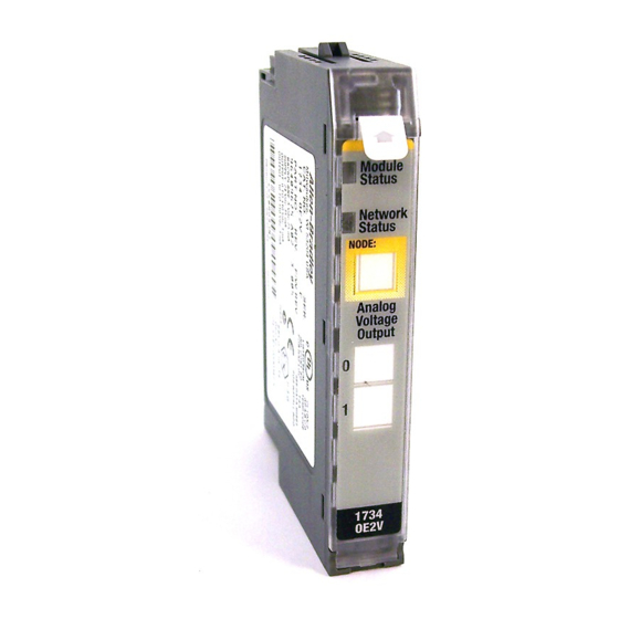
- Page 15 POINT I/O 2 Current Output and 2 Voltage Output Analog Modules 1734-OE2V POINT I/O 2 Voltage Output Analog Module Module Status Module Status Network Status Network Status NODE: Analog Voltage Status of Output 0 Output Status of Output 1 1734 OE2V Output 0 Connection Output 1 Connection...
-
Page 16: Troubleshoot With Indicators
Chassis Ground Common Supply 24V DC power is provided by the internal field power bus. Troubleshoot with Indicators Use the status indicators and tables to troubleshoot your module. 1734-OE2C POINT I/O 2 Current Module Module Status Output Analog Module Status... - Page 17 Device received and accepted an Identify Communication Faulted Request - long protocol message. Channel Status Indication Probable Cause Probable Cause 1734-OE2C 1734-OE2V Module is in CAL mode. Green Normal operation is present with channel actively controlling outputs. Publication 1734-IN002E-EN-E - October 2016...
-
Page 18: Placing Series C Analog Current Output Modules
18 POINT I/O 2 Current Output and 2 Voltage Output Analog Modules Channel Status Indication Probable Cause Probable Cause 1734-OE2C 1734-OE2V Flashing Green Channel is being calibrated. Flashing Red Open wire or no field power is present. A low or high clamp is present. - Page 19 POINT I/O 2 Current Output and 2 Voltage Output Analog Modules Output Specifications Output Specifications 1734-OE2C 1734-OE2V Current Load on — Voltage Output Resistive Load on 0...750Ω — Current Output Conversion Type Digital to analog converter Conversion Rate 16μs 20μs...
- Page 20 20 POINT I/O 2 Current Output and 2 Voltage Output Analog Modules General Specifications Attribute 1734-OE2C 1734-OE2V Enclosure Type Rating None (open-style) Wire Size 0.25... 2.5 mm (22...14 AWG) solid or stranded copper wire rated at 75 °C (167 °F) or greater 1.2 mm (3/64 in.) insulation max...
- Page 21 POINT I/O 2 Current Output and 2 Voltage Output Analog Modules Environmental Specifications Attribute 1734-OE2C 1734-OE2V Radiated RF Immunity IEC 61000-4-3: 10 V/m with 1kHz sine-wave 80%AM from 80 MHz...2700 MHz 10 V/m with 200 Hz 50% Pulse 100%AM at 900 MHz...
- Page 22 RA-DU002, available at http://www.rockwellautomation.com/literature/. Allen-Bradley, Rockwell Automation, POINT I/O, and TechConnect are trademarks of Rockwell Automation, Inc. Trademarks not belonging to Rockwell Automation are property of their respective companies. Rockwell Automation maintains current product environmental information on its website at http://www.rockwellautomation.com/rockwellautomation/about-us/sustainability-ethics/product-environmental-compliance.page.
Need help?
Do you have a question about the 1734-OE2C and is the answer not in the manual?
Questions and answers