Allen-Bradley ControlNet 1786-RPFM Installation Instructions Manual
Modular repeater medium-distance fiber module
Hide thumbs
Also See for ControlNet 1786-RPFM:
- Installation instructions manual (20 pages) ,
- Installation instructions manual (20 pages) ,
- Product information (6 pages)
Table of Contents
Advertisement
Quick Links
0
ControlNet Modular Repeater
Medium-distance Fiber Module
(Cat. No. 1786-RPFM)
Use this document as a guide when you install a ControlNet
fiber module for medium distances:
To install the module, read these sections:
Section
For this information, refer to these sections:
Section
Installation Instructions
Installation Instructions
AB Spares
repeater
Page
2
3
4
8
12
Page
10
11
11
14
1786-5.11 - February 1998
Advertisement
Table of Contents

Related Manuals for Allen-Bradley ControlNet 1786-RPFM


Summary of Contents for Allen-Bradley ControlNet 1786-RPFM
-
Page 1: Table Of Contents
Installation Instructions Installation Instructions ControlNet Modular Repeater Medium-distance Fiber Module (Cat. No. 1786-RPFM) Use this document as a guide when you install a ControlNet repeater fiber module for medium distances: To install the module, read these sections: Section Page About The Fiber Module European Union Directive Compliance Mounting The Fiber Module Wiring The Fiber Module... -
Page 2: About The Fiber Module
ControlNet Modular Repeater Medium-distance Fiber Module About The Fiber Module Use this module when a medium-distance (distances of 3000m/9843ft) fiber link is required between two ControlNet products. This fiber link provides ground isolation between nodes and is less susceptible to noisy environments than traditional cooper media. -
Page 3: European Union Directive Compliance
Programmable Controllers, Part 2 – Equipment Requirements and Tests. For specific information that the above norm requires, see the appropriate sections in this manual, as well as the following Allen-Bradley publications: Industrial Automation Wiring and Grounding Guidelines, publication 1770-4.1 Guidelines for Handling Lithium Batteries, publication AG-5.4... -
Page 4: Mounting The Fiber Module
ControlNet Modular Repeater Medium-distance Fiber Module Mounting The Fiber Module To mount the module on the DIN rail: 1. Position the module on a 35 x 7.5mm DIN rail (Allen-Bradley part number 199-DR1; 46277-3; EN 50022) at a 30 angle. - Page 5 ControlNet Modular Repeater Medium-distance Fiber Module 3. Press the module down onto the DIN rail until flush. The locking tab should snap into position and lock the module to the DIN rail. 4. If the module does not snap into position, use a screwdriver or similar device to move the locking tab down while pressing the module flush onto the DIN rail.
- Page 6 ControlNet Modular Repeater Medium-distance Fiber Module 5. Remove the protective backplane cap as shown in “Removing the Protective Caps” on page 7. 6. Once attached to the DIN rail, slide modules to the left to mate with the repeater adapter or another repeater module. 30043–M ATTENTION: Make certain that the adapter and repeater modules are secured together with DIN rail anchors.
- Page 7 ControlNet Modular Repeater Medium-distance Fiber Module Removing the Protective Caps 1. Remove the protective caps from the fiber channels that will be used. 2. Save the caps for future use. Protective backplane DIN rail Protective cap 30049–M The left side of the module (not shown here) also contains a backplane connector Then: a channel is not going to be used keep protective caps on channels to protect...
-
Page 8: Wiring The Fiber Module
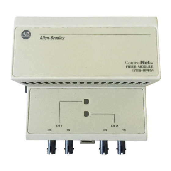
ControlNet Modular Repeater Medium-distance Fiber Module Wiring The Fiber Module If only one channel is wired, you can use Channel 1 or Channel 2. To wire the module for Channel 1: 1. Connect to Receive ST. a. Align the knob of the ST cable connector with the groove of the ST module connector, and insert the connector into Channel 1 Channel 2... - Page 9 ControlNet Modular Repeater Medium-distance Fiber Module To wire the module for Channel 2: 1. Repeat the steps for Channel 1 and refer to the following figure. 1786–RPA 1786–RPFM 1786–RPA 1786–RPFM CH1 CH2 CH1 CH2 Important: Be sure the fiber connected to A(receive) on one 1786–RPFM is connected to B(transmit) on the other 1786–RPFM.
-
Page 10: Indicators
ControlNet Modular Repeater Medium-distance Fiber Module Indicators The figure below identifies indicators on the module: Channel 1 status Channel 2 status The table below defines Channel 1 and Channel 2 (individually) status indications: Status Indicator Probable Cause No power or module is faulted Green Channel operational Flashing Green/Off... -
Page 11: Related Publications
ControlNet Modular Repeater Medium-distance Fiber Module Related Publications The table below lists publications that you may want to refer to for additional information: Publication Publication Number Industrial Automation Wiring and Grounding Guidelines 1770-4.1 ControlNet Coax Tap Installation Instructions 1786-5.7 ControlNet Cable System Planning and Installation Manual 1786-6.2.1 ControlNet Cable System Component List AG-2.2... -
Page 12: Csa Hazardous Location Approval
Example of the CSA certification product label To comply with CSA certification for use in hazardous locations, the following information becomes a part of the product literature for CSA-certified Allen-Bradley industrial control products. This equipment is suitable for use in Class I, Division 2, Groups A, B, C, D, or non-hazardous locations only. - Page 13 Pour satisfaire à la certification de la CSA dans des endroits dangereux, les informations suivantes font partie intégrante de la documentation des produits industriels de contrôle Allen-Bradley certifiés par la CSA. Cet équipement convient à l’utilisation dans des emplacements de Classe 1, Division 2, Groupes A, B, C, D, ou ne convient qu’à...
-
Page 14: Specifications
1786–RPFM ST terminations. ControlNet is a trademark of ControlNet International is a trademark of AT&T. Worldwide representation. 1786-5.11 — February 1998 955131-12 1786-5.11 — February 1998 Supersedes 1786-5.11 – July 1997 Copyright 1997 Allen-Bradley Company, Inc. Printed i USA...
Need help?
Do you have a question about the ControlNet 1786-RPFM and is the answer not in the manual?
Questions and answers